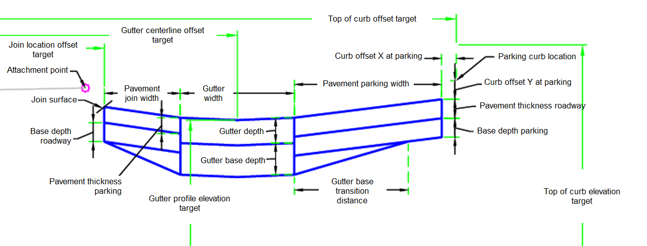
The ParkingAdjacentToRoad subassembly builds a parking area adjacent to an existing roadway. The parking includes a paved area of the existing roadway, a gutter, and a parking pavement. The parking pavement ties into a proposed curb elevation and top of curb location.
Attachment
The attachment point is at a point at the center of the roadway. This component can be attached to either the left or right side.
Input Parameters
|
Parameter |
Description |
Type |
Default |
|---|---|---|---|
| Side | Specifies which side to place the subassembly | Left / Right | Right |
| Gutter Width | Entire width of the gutter | Numeric, positive |
3 ft 1 m |
| Gutter Depth | Gutter depth | Numeric, positive |
8 in 200 mm |
| Pavement Thickness Parking | AC pavement thickness | Numeric, positive |
2 in 50 mm |
| Gutter Base Transition Distance | Transition of thicker base at gutter | Numeric, positive |
3 ft 1 m |
| Curb Offset Y At Parking | Curb offset Y at back of parking | Numeric |
-0.5 ft -0.150 m |
| Curb Offset X At Parking | Curb offset X at back of parking | Numeric |
-0.625 ft -0.19 m |
| Pavement Parking Width | Pavement parking width | Numeric, positive |
20.5 ft 6.25 m |
| Gutter Base Depth | Pavement join width | Numeric, positive |
2 ft 0.6 m |
| Base Depth Parking | Base depth under gutter | Numeric, positive |
6 in 150 mm |
| Base Depth Roadway | Base depth roadway | Numeric, positive |
10 in 250 mm |
| Pavement Thickness Roadway | Pavement thickness roadway | Numeric, positive |
3 in 80 mm |
Target Parameters
This section lists the parameters in this subassembly that can be mapped to one or more target objects. For more information, see To Specify Corridor Targets.
|
Parameter |
Description |
Status |
|---|---|---|
| Join Location | Used to determine the join width from the attachment point. The following object types can be used as targets for specifying the width: alignments, polylines, feature lines, or survey figures. | Required |
| Join Surface | Used to determine the join elevation. The following object types can be used as targets for specifying the surface: surfaces. | Required |
| Top of Curb Offset | Used to determine the top of curb elevation of the tie-in location of parking curb. The following object types can be used as targets for specifying the elevation: profiles, 3D polylines, feature lines, or survey figures. | Required |
| Top of Curb Profile | Used to determine the offset location for curb and gutter. The following object types can be used as targets for specifying the elevation: profiles, 3D polylines, feature lines, or survey figures. | Required |
| Gutter Centerline | Used to determine the gutter centerline location. The following object types can be used as targets for specifying the width: alignments, polylines, feature lines, or survey figures. | Required |
| Gutter Profile | Used to determine the centerline elevation of the gutter. The following object types can be used as targets for specifying the elevation: profiles, 3D polylines, feature lines, or survey figures. | Required |
Runtime Logical Assignments
None.
Output Parameters
|
Parameter |
Description |
Type |
|---|---|---|
| Lane Slope | Lane slope | Numeric |
Behavior
The initial reference point is set at the attachment point. The top of curb profile and offset values are found to determine the location of the outer edge of the parking pavement. The join location is determined from the join location target. The join elevation is found based on the join location and the join surface target at this point. The gutter location and gutter elevation are determined from the set targets. The gutter geometry is then built based on the input parameters. The pavement join geometry is built from the target join elevations and input parameters. Then the parking pavement is built using the target values and input parameters.
Layout Mode Operation
In layout mode, this subassembly displays all links using the width and depth input parameters and assumed target values.
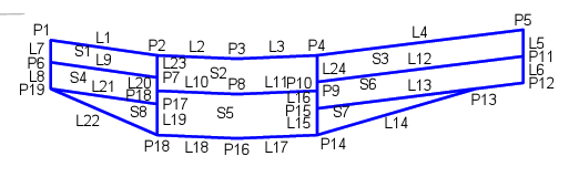
Point, Link, and Shape Codes
The following table lists the point, link, and shape codes for this subassembly that have codes assigned to them. Point, link, or shape codes for this subassembly that do not have codes assigned are not included in this table.
|
Point, Link, or Shape |
Code |
Description |
|---|---|---|
| P1 | Join | Pavement join location |
| P2 | Gutter_Edge | Gutter edge |
| P3 | FL | Flowline of gutter |
| P4 | ETW | Edge of traveled way |
| P5 | FS | Finish surface |
| P12, P15, P17, P19 | Base | Base |
| L1, L4 | Top, Pave | Top of pavement |
| L2, L3 | Top, Gutter | Top of gutter |
| L9, L12 | Pavement | Bottom of pavement thickness |
| L10, L11 | Gutter | Bottom of gutter |
| L13, L14, L17, L18, L21, L22 | Datum | |
| S1, S3 | Pave | |
| S2, | Gutter | |
| S4-S6, S7, S8 | Base |
Coding Diagram