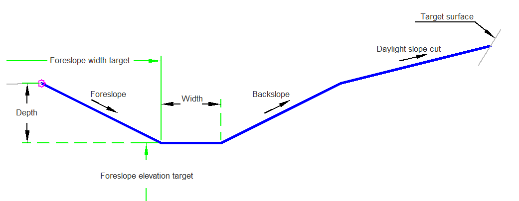
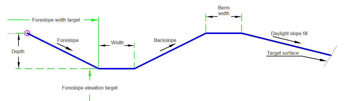
The SlopeDitch subassembly creates a ditch with backslope and foreslopes. In cut, it daylights to the existing ground. In fill, a berm is created and then daylights.
Case Cut:
Case Fill:
Attachment
The attachment point is the innermost point on the grading links preceding the ditch.
Input Parameters
|
Parameter |
Description |
Type |
Default |
|---|---|---|---|
| Side | Specifies which side to place the subassembly. | Left/Right | Right |
| Depth | Depth of the ditch measured from the ditch out to the hinge point out. | Numeric |
3 ft 1 m |
| Width | Width of the bottom of the ditch. | Numeric, positive |
2 ft 0.6 m |
| Foreslope | Slope of the front-of-ditch link (x : 1). This link is always inserted downwards. | Numeric, positive | 2 (: 1) |
| Backslope | Slope of the back-of-ditch link (x : 1). This link is always inserted upwards. | Numeric, positive | 2 (: 1) |
| Berm Width | Width of the berm after the backslope. | Numeric, positive |
2 ft 0.6 m |
| Daylight Cut Slope | The slope for normal daylighting in cut conditions. | Numeric, positive | 3 (: 1) |
| Daylight Fill Slope | The slope for normal daylighting in fill conditions. | Numeric, positive | 4 (: 1) |
Target Parameters
This section lists the parameters in this subassembly that can be mapped to one or more target objects. For more information, see To Specify Corridor Targets.
|
Parameter |
Description |
Status |
|---|---|---|
| Daylight Surface | Name of the daylighting surface. The following object types can be used as targets for specifying the surface: surfaces. | Optional |
| Foreslope Elevation | May be used to override the foreslope slopes and widths. The following object types can be used as targets for specifying this elevation: profiles, 3D polylines, feature lines, or survey figures. | Optional |
| Foreslope Width | May be used to override the foreslope width. The following object types can be used as targets for specifying this: alignments, polylines, feature lines, or survey figures. | Optional |
Runtime Logical Assignments
None.
Output Parameters
None.
Behavior
The ditch foreslope, bottom, and backslope of the ditch are created. The subassembly is then determined to be in cut or fill at the top of the backslope. If in fill, a berm is created and then daylights. If in cut, the daylight link is created using the daylight slope.
Layout Mode Operation
In layout mode the subassembly displays the links comprising the ditch and berm in fill.
Point, Link, and Shape Codes
The following table lists the point, link, and shape codes for this subassembly that have codes assigned to them. Point, link, or shape codes for this subassembly that do not have codes assigned are not included in this table.
|
Point, Link, or Shape |
Code |
Description |
|---|---|---|
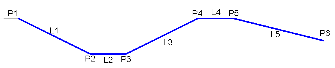
| P1 | Hinge, Top | |
| P2 | Ditch_In, Top | |
| P3 | Ditch_Out, Top | |
| P4 | Hinge, Top | |
| P5 | Daylight, Top | |
| P6 | Berm_Out, Top | |
| P7 | Daylight, Top | |
| L1 | Top, Datum, Ditch, Foreslope | |
| L2 | Top, Datum, Ditch | |
| L3 | Top, Datum, Ditch, Backslope | |
| L4 | Top, Datum, Ditch, Daylight | |
| L5 | Top, Datum, Ditch | |
| L6 | Top, Datum, Ditch, Daylight |
Coding Diagram
Case Cut:
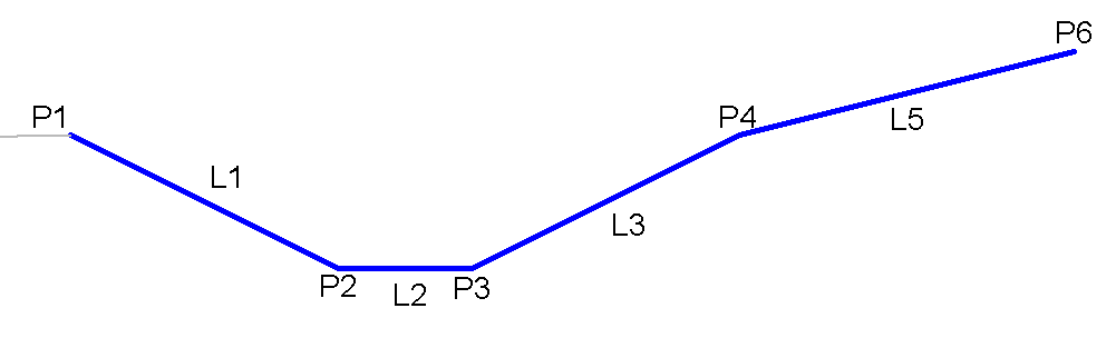
Case Fill: