The ClarkCountyBasicDaylight subassembly inserts links to create cut or fill catch slopes with a shoulder. You can define a ditch in cut situations.
You should verify that the dimensions used match your interpretation of the standard plan.
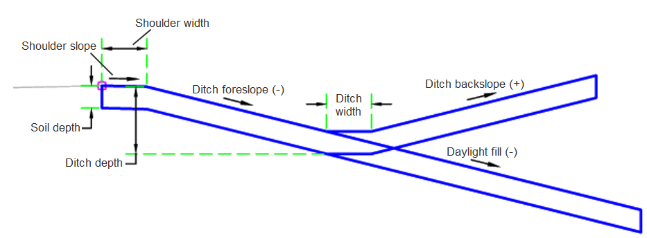
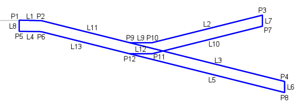
Case 1: With Ditch
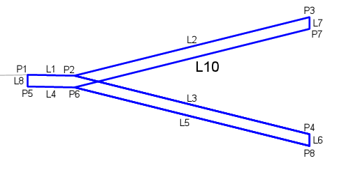
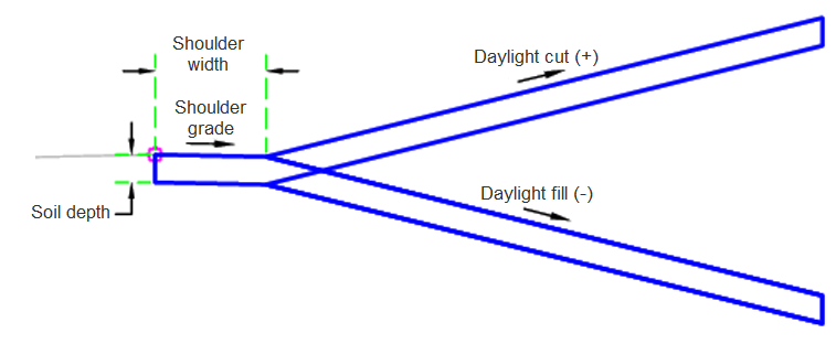
Case 2: Without Ditch
Attachment
The attachment point is at the inside edge of the initial cut or fill slope. This component can be attached to either the left or right side.
Input Parameters
|
Parameter |
Description |
Type |
Default |
|---|---|---|---|
| Side | Specifies which side to place the subassembly | Left / Right | Right |
| Daylight_Cut (+) | Daylight Cut Slope | Numeric, positive | 4 ( : 1) |
| Daylight_Fill (-) | Daylight Fill Slope | Numeric, negative | -4 ( : 1) |
| Shoulder Width | Optional Shoulder Width | Numeric, positive |
1 ft 0.3 m |
| Shoulder Slope | Only if shoulder is used | Numeric | -2 (%) |
| Soil Depth | Optional Soil Depth | Numeric, positive |
0.5 ft 0.15 m |
| Ditch Depth | Ditch depth from attach point | Numeric |
1 ft 0.3 m |
| Ditch ForeSlope (-) | Ditch Fore Slope | Numeric | -4 ( : 1) |
| Ditch BackSlope (+) | Dich Back Slope | Numeric, positive | 4 ( :1 ) |
Target Parameters
This section lists the parameters in this subassembly that can be mapped to one or more target objects. For more information, see To Specify Corridor Targets.
|
Parameter |
Description |
Status |
|---|---|---|
| Daylight Surface | Name of the daylighting surface. The following object types can be used as targets for specifying the surface: surfaces. | Required |
| Elevation | May be used to override the ditch bottom elevation. The following object types can be used as targets for specifying the elevation: profiles, 3D polylines, feature lines, or survey figures. | Optional |
Runtime Logical Assignments
None.
Output Parameters
None.
Behavior
The initial shoulder or hinge point is set at the attachment point. If the shoulder is built if the shoulder width is larger than zero. The hinge point elevation is checked against the target surface to determine if the section is in the cut or fill condition. If in cut, the ditch is determined if it needs to be built. Then an intercept is calculated to the target surface using the given Daylight Slope.
Layout Mode Operation
In layout mode, this subassembly draws the initial fill slope to 5 ft (1.5 m).
Point, Link, and Shape Codes
The following table lists the point, link, and shape codes for this subassembly that have codes assigned to them. Point, link, or shape codes for this subassembly that do not have codes assigned are not included in this table.
|
Point, Link, or Shape |
Code |
Description |
|---|---|---|
| P1 | Shldr | When shoulder is present |
| P1 | Hinge | When no shoulder is present |
| P2 | Shldr | Shoulder |
| P3 | Daylight, Daylight_Cut | Daylight point, and daylight point for the cut condition |
| P4 | Daylight, Daylight_Fill | Daylight point, and daylight point for the fill condition |
| P9 | Ditch_In | Inside bottom of ditch |
| P10 | Ditch_Out | Outside bottom of ditch |
| L1 | Top, Shldr | Top of Shoulder |
| L2 | Daylight, Daylight_Cut,Top, Datum | Daylight link for cut section. Datum code is omitted when soil depth is greater than 0. |
| L3 | Daylight, Daylight_Fill, Top, Datum | Daylight link for fill section. Datum code is omitted when soil depth is greater than 0. |
| L11 | Top, Datum, Ditch | Ditch link. Datum code is omitted when soil depth is greater than 0. |
| L4, L5, L10, L13 | Datum | Bottom link code |
| S1 | Soil | Soil Shape Code |
Coding Diagram
Case 1: With Ditch
Case 1: Without Ditch