The BioRetention subassembly inserts links to create a bioretention area with three layers and an optional underdrain. The subassembly is based on requirements of the County of Los Angeles Low Impact Development Standards Manual, dated February 2014.
You should verify that the dimensions used match your interpretation of the referenced document.
Attachment
The attachment point is at the middle top of the bioretention.
Input Parameters
|
Parameter |
Description |
Type |
Default |
|---|---|---|---|
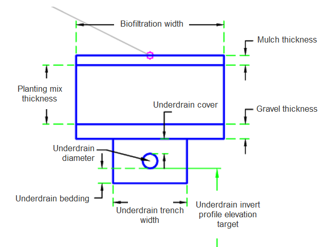
| Biofiltration Width | Biofiltration width | Numeric, positive |
5 ft 1.5 m |
| Mulch Thickness | Thickness of mulch | Numeric, positive |
0.33 ft 0.10 m |
| Planting Mix Thickness | Planting mix thickness under mulch | Numeric, positive |
2.0 ft 0.6 m |
| Gravel Thickness | Gravel thickness under planting mix | Numeric, positive |
0.5 ft 0.15 m |
| Include Underdrain | Include underdrain to remove water | Yes/ No | Yes |
| Underdrain Diameter | Underdrain diameter | Numeric, positive |
0.5 ft 0.15 m |
| Underdrain Cover | Underdrain cover | Numeric, positive |
0.5 ft 0.15 m |
| Underdrain Bedding | Bedding under the underdrain pipe | Numeric, positive |
0.5 ft 0.15 m |
| Underdrain Trench Width | Underdrain trench width | Numeric, positive |
2.5 ft 0.75 m |
Target Parameters
This section lists the parameters in this subassembly that can be mapped to one or more target objects. For more information, see To Specify Corridor Targets.
|
Parameter |
Description |
Status |
|---|---|---|
| Underdrain Invert Profile | May be used to override the fixed invert elevation of the underdrain pipe. The following object types can be used as targets for specifying the elevation: profiles, 3D polylines, feature lines, or survey figures. | Optional |
Runtime Logical Assignments
None.
Output Parameters
None.
Behavior
The initial point is set at the attachment point. The subassembly builds a mulch layer followed by a planting mix layer, followed by a gravel layer. If set to include an underdrain pipe the subassembly builds an underdrain pipe and pipe bedding.
Layout Mode Operation
In layout mode, this subassembly draws the bioretention using the input parameters.
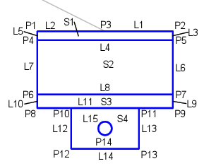
Point, Link, and Shape Codes
The following table lists the point, link, and shape codes for this subassembly that have codes assigned to them. Point, link, or shape codes for this subassembly that do not have codes assigned are not included in this table.
|
Point, Link, or Shape |
Code |
Description |
|---|---|---|
| P1,P3 | BioretentionTop | Top of bioretention |
| P2 | BioretentionCenter | Center of bioretention |
| P4,P5 | Mulch | Bottom point of Mulch layer |
| P6,P7 | Plant_Mix | Bottom point of Plant Mix layer |
| P8, P9 | Gravel | Bottom point of Gravel |
| P10-P13 | Underdrain | Points around underdrain |
| P14 | Invert | Invert of underdrain pipe |
| L1-L2 | Bioretention,Top | Bioretention top layer |
| L4 | Mulch | Bottom of mulch layer |
| L8 | Plant_Mix | Bottom of Plant Mix layer |
| L11 | Gravel,Datum | Bottom of Gravel layer |
| L14 | Underdrain,Datum | Bottom of underdrain layer |
| S1 | Mulch | Mulch area |
| S2 | Planting_Mix | Planting Mix area |
| S3 | Gravel | Gravel area |
| S4 | UnderdrainPipe | Underdrain pipe layer |
Coding Diagram