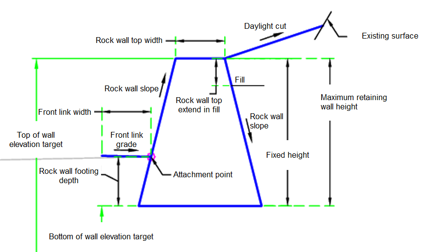
The RockRetainingWall subassembly inserts links to create a rock retaining wall to retain soil.
Attachment
The attachment point is at either the rock face or a distance away from the way location based on the Front Link input parameters.
Input Parameters
|
Parameter |
Description |
Type |
Default |
|---|---|---|---|
| Side | Specifies which side to place the subassembly | Left / Right | Right |
| Rock Wall Footing Depth | Footing depth of the rock wall | Numeric |
1.0 ft 0.30 m |
| Rock Wall Slope | Rock wall slope | Numeric | 0.25 ( : 1) |
| Rock Wall Top Width | Rock wall top width | Numeric, positive |
1 ft 0.30 m |
| Daylight Cut | Daylight cut | Numeric, positive | 3 ( : 1) |
| Maximum Retaining Wall Height | Maximum retaining wall height | Numeric, positive |
6 ft 1.8 m |
| Use fixed height | Use fixed height | Yes / No | Yes |
| Fixed Height | A fixed height if specified to be used | Numeric, positive |
3 ft 1.0 m |
| Use Daylight | Use daylight | Yes / No | Yes |
| Front Link Grade | Front link grade | Numeric | -2% |
| Front Link Code | Front link code | String | Top, Pave |
| Front Link Width | Front link width | Numeric, positive |
0.25 ft 0.08 m |
| Use Front Link | Use front link | Yes / No | Yes |
| Rock Wall Top Extend In Fill | Rock wall top extend in fill | Numeric, positive |
1 ft 0.3 m |
Target Parameters
This section lists the parameters in this subassembly that can be mapped to one or more target objects. For more information, see To Specify Corridor Targets.
|
Parameter |
Description |
Status |
|---|---|---|
| Existing Surface | Name of the daylighting surface. The following object types can be used as targets for specifying the surface: surfaces. | Optional |
| Top of Wall | May be used to override the top of wall elevation of the rock wall. In order to be used, the Fixed Height Input Parameter must be set to No. The following object types can be used as targets for specifying the elevation: profiles, 3D polylines, feature lines, or survey figures. | Optional |
| Bottom of Wall | May be used to override the bottom of wall elevation. The following object types can be used as targets for specifying the elevation: profiles, 3D polylines, feature lines, or survey figures. | Optional |
Runtime Logical Assignments
None.
Output Parameters
None.
Behavior
The initial point is set at the attachment point. The front link is built if Use Front Link is set to Yes. The rock wall is then built.
If Use Fixed Height is set to Yes the rock wall is built using the input parameters. If the Bottom of Wall profile is set then the top of wall height is determined by the Bottom of Wall profile elevation plus the fixed height. The top of wall target is not used.
Cut Condition:
If Use Fixed Height is set to No the rock wall is built using the input parameters. The Top of Wall Target controls the top of wall elevation. If the Top of Wall Target is not set then the Top of Wall elevation is the existing ground elevation at the inside edge of the wall.
Fill Condition:
If Use Fixed Height is set to No the rock wall is built using the input parameters. The Top of Wall Target controls the top of wall elevation. If the Top of Wall Target is not set then the Top of Wall elevation is the distance between the attachment point and the Rock Wall Top Extend in Fill input parameter.
In all conditions the wall height is calculated and compared to the Maximum Retaining Wall Height. If the value is exceeded then an error message is sent to the Event Viewer.
Layout Mode Operation
In layout mode, this subassembly draws the rock retaining wall with the input parameters.
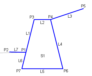
Point, Link, and Shape Codes
The following table lists the point, link, and shape codes for this subassembly that have codes assigned to them. Point, link, or shape codes for this subassembly that do not have codes assigned are not included in this table.
|
Point, Link, or Shape |
Code |
Description |
|---|---|---|
| P1 | Face_Wall | Face of the wall |
| P2 | ETW | Edge of traveled way |
| P3, P4, P6, P7 | Rock Wall | Rock wall |
| P5 | Daylight | Daylight |
| L1-L2 | Rock Wall, Top | Top of the rock wall |
| L3 | Daylight, Top, Datum | Daylight link |
| L4, L6 | Rock Wall | Rock wall |
| L5 | Rock Wall, Datum | Bottom of rock wall |
| L7 | Top, Pave | Pavement top |
| S1 | Rock Wall | Rock wall area |
Coding Diagram