The VegetatedFilterStrip subassembly inserts links to create a vegetated filter strip to treat storm water.
Attachment
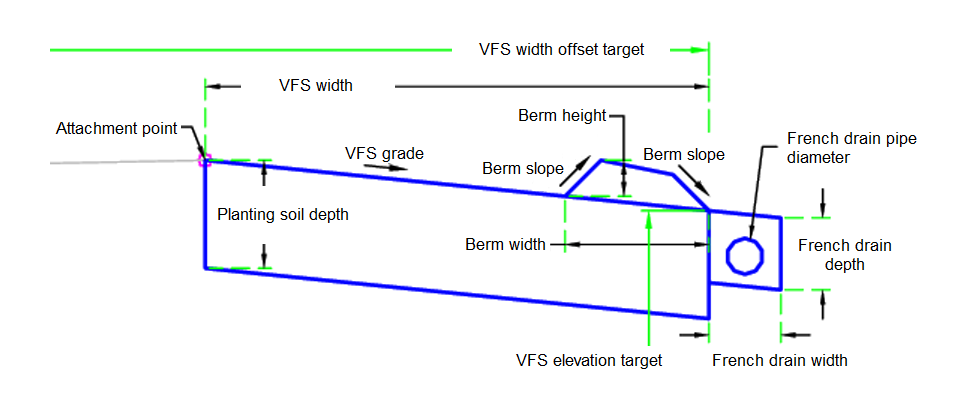
The attachment point is at the inside edge of the Vegetated Filter Strip. This component can be attached to either the left or right side.
Input Parameters
|
Parameter |
Description |
Type |
Default |
|---|---|---|---|
| Side | Specifies which side to place the subassembly | Left / Right | Right |
| Include French Drain Outlet | Include French drain outlet at end of filter | Yes / No | Yes |
| Berm Slope | Slope of berm | Numeric, positive | 1 ( : 1) |
| Berm Width | Width of berm | Numeric, positive |
2 ft 0.60 m |
| Berm Height | Height of berm | Numeric, positive |
0.5 ft 0.15 m |
| Include Berm at Toe | Include berm at toe to contain water | Yes / No | Yes |
| Planting Soil Depth | Planting soil depth | Numeric, positive |
1.5 ft 0.45 m |
| Include Planting Soil | Include planting soil | Yes / No | Yes |
| VFS Grade | Vegetated filter strip grade | Numeric | -10% |
| VFS Width | Vegetated filter strip width | Numeric, positive |
15 ft 4.5 m |
| French Drain Pipe Diameter | French drain pipe diameter | Numeric, positive |
0.5 ft 0.15 m |
| French Drain Depth | French drain depth | Numeric, positive |
1 ft 0.3 m |
| French Drain Width | French drain width | Numeric, positive |
1 ft 0.3 m |
Target Parameters
This section lists the parameters in this subassembly that can be mapped to one or more target objects. For more information, see To Specify Corridor Targets.
|
Parameter |
Description |
Status |
|---|---|---|
| VFS Width | May be used to override the vegetated filter strip offset value and tie the edge to an offset alignment. The following object types can be used as targets for specifying the width: alignments, polylines, feature lines, or survey figures. | Optional |
| VFS Elevation | May be used to override the vegetated filter strip and tie the elevation to the elevation of a profile. The following object types can be used as targets for specifying the elevation: profiles, 3D polylines, feature lines, or survey figures. | Optional |
Runtime Logical Assignments
None.
Output Parameters
None.
Behavior
Starting at the attachment point, a finish grade surface and parallel subgrade are inserted using the given width and depth. Vertical links close the shape at either end of the vegetated filter strip. An optional berm is built at the far end of the vegetated filter strip. An optional French drain is constructed at the end of the vegetated filter strip.
Layout Mode Operation
In layout mode, this subassembly displays all links using the input parameters.
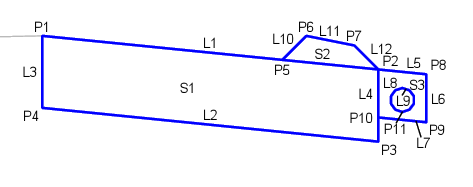
Point, Link, and Shape Codes
The following table lists the point, link, and shape codes for this subassembly that have codes assigned to them. Point, link, or shape codes for this subassembly that do not have codes assigned are not included in this table.
|
Point, Link, or Shape |
Code |
Description |
|---|---|---|
| P2 | Filter_Outside | Outside edge of vegetated filter strip |
| P5-P7 | Berm | |
| P11 | Pipe_Invert | Invert of the French drain pipe |
| L1 | Filter, Top | Top of vegetated filter strip |
| L2, L7 | Datum | |
| L5 | Top, FrenchDrain | Top of French drain |
| L9 | Pipe | |
| L10-12 | Berm | |
| S1 | VFS | Vegetated filter strip |
| S2 | Berm | |
| S3 | FrenchDrain | French drain |
Coding Diagram