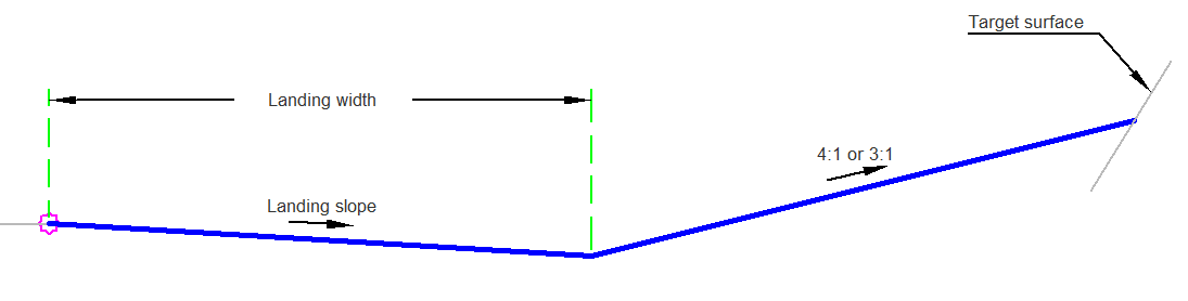
The SimpleCutWithLanding subassembly allows a simple landing/shoulder with a cut option. The subassembly only daylights in a cut situation.
Attachment
The attachment point is the innermost point on the grading links preceding the landing.
Input Parameters
|
Parameter |
Description |
Type |
Default |
|---|---|---|---|
| Side | Specifies which side to place the subassembly. | Left/Right | Right |
| Landing Width | Width of the landing. | Numeric, positive |
5 ft 1.5 m |
| Landing Slope | % slope of the landing. | Numeric | -6 ( % ) |
Target Parameters
This section lists the parameters in this subassembly that can be mapped to one or more target objects. For more information, see To Specify Corridor Targets.
|
Parameter |
Description |
Status |
|---|---|---|
| Daylight Surface | Name of the daylighting surface. The following object types can be used as targets for specifying the surface: surfaces. | Optional |
Runtime Logical Assignments
None.
Output Parameters
None.
Behavior
The landing is drawn using the input parameters. The height to daylight is then calculated. If the distance is less than 25 ft (7.5 m) a daylight slope of 4:1 is used. If the height is less than 35 ft (10.5 m) a daylight slope of 3:1 is used. Otherwise a daylight slope of 2:1 is used.
If in fill, the daylight slope is not created.
Layout Mode Operation
In layout mode the subassembly displays the links comprising the landing and a link for the daylight in cut.
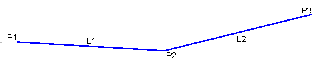
Point, Link, and Shape Codes
The following table lists the point, link, and shape codes for this subassembly that have codes assigned to them. Point, link, or shape codes for this subassembly that do not have codes assigned are not included in this table.
|
Point, Link, or Shape |
Code |
Description |
|---|---|---|
| P1 | Top, Hinge | |
| P2 | Top, LandingOuter | Outer Landing Point |
| P3 | Daylight_point | Daylight Point |
| L1, L2 | Top |
Coding Diagram