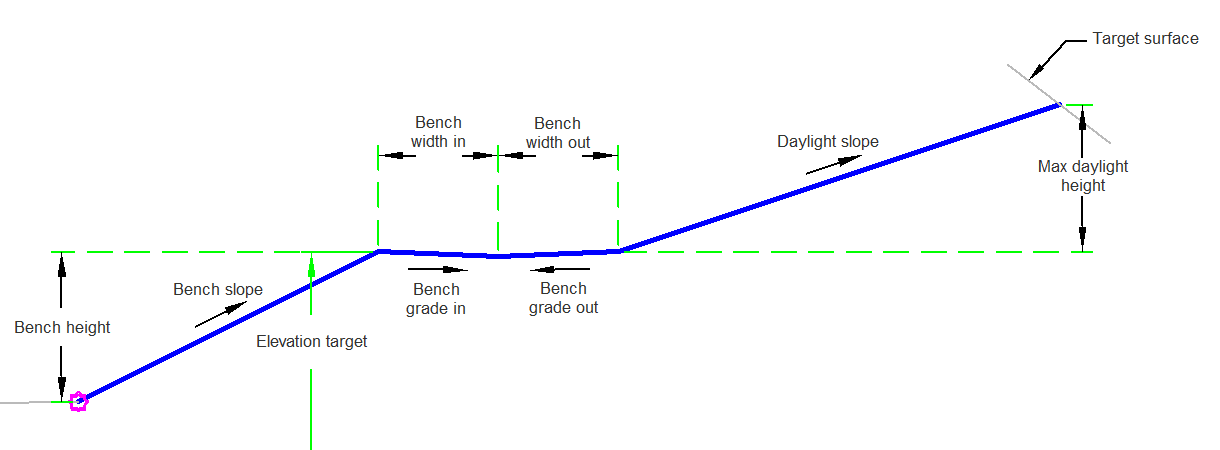
The BasicBenchTargetOneElevation is a simple bench subassembly that inserts links to create cut or fill catch slopes with one bench.
You can define a swale width and depth at the benches as well as target a single surface at the bench point.
Attachment
The attachment point is at the inside edge of the initial cut or fill slope. This component can be attached to either the left or right side.
Input Parameters
|
Parameter |
Description |
Type |
Default |
|---|---|---|---|
|
Side |
Specifies which side to place the subassembly. |
Left / Right |
Right |
|
Max Daylight Height |
The maximum allowable height for the cut and fill daylight link without benching. |
Numeric |
15.0 ft 4.5 m |
|
Bench Height |
The maximum allowable height for a bench before a new bench. |
Numeric |
10.0 ft 3.0 m |
|
Bench Slope |
The slope between benches. |
Numeric, positive |
1 (: 1) |
|
Bench Grade In |
The +/- % slope of the bench. Positive slopes are upward in the direction of increasing offset. |
Numeric |
4 (%) |
|
Bench Width In |
The width of the bench to the bench flowline |
Numeric, positive |
4 ft 1.2 m |
|
Bench Grade Out |
The +/- % slope of the bench. Positive slopes are upward in the direction of increasing offset. |
Numeric |
4 (%) |
|
Bench Width Out |
The width of the bench from the bench flowline. |
Numeric |
4 ft 1.2 m |
|
Daylight Slope |
The daylight slope. |
Numeric, positive |
2 (: 1) |
Target Parameters
This section lists the parameters in this subassembly that can be mapped to one or more target objects. For more information, see To Specify Corridor Targets.
|
Parameter |
Description |
Status |
|---|---|---|
|
Daylight Surface |
Name of the daylighting surface. The following object types can be used as targets for specifying the surface: surfaces. | Required |
|
Elevation Target |
May be used to override the bench elevation and tie to a profile. The following object types can be used as targets for specifying this: profiles, 3D polylines, feature lines, or survey figures. | Optional |
Runtime Logical Assignments
None.
Output Parameters
None.
Behavior
The initial hinge point is set at the attachment point. The hinge point elevation is checked against the target surface to determine if the section is in the cut or fill condition. The first link is then built to the target elevation or if not, set to the bench height. The bench links are added. The hinge point is reset to the outside edge of the bench and a daylight link is then found.
Layout Mode Operation
In layout mode, this subassembly draws a cut slope with a bench.
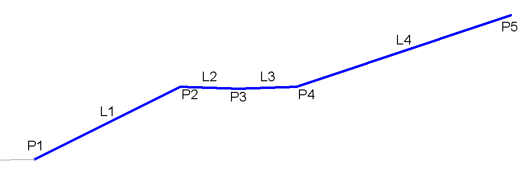
Point, Link, and Shape Codes
The following table lists the point, link, and shape codes for this subassembly that have codes assigned to them. Point, link, or shape codes for this subassembly that do not have codes assigned are not included in this table.
|
Point, Link, or Shape |
Code |
Description |
|---|---|---|
| P1 - P5 | Top | |
| P5 | Daylight | Daylight point, and daylight point for either the cut or fill condition. This only applies to the actual daylight point. |
| L1 - L4 | Top |
Coding Diagram