The Dam subassembly inserts links to create a representation of a dam. A progress profile is present to adjust the dam geometry to reflect the progress.
Attachment
The attachment point is at the center of the dam.
Input Parameters
|
Parameter |
Description |
Type |
Default |
|---|---|---|---|
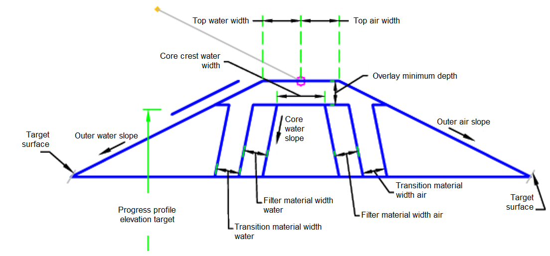
| Outer Water Slope | Outer slope of dam facing the impounded water | Slope | 2 ( : 1) |
| Outer Air Slope | Outer slope facing away from impounded water | Slope | 2 ( : 1) |
| Core Water Slope | Core slope of dam facing the impounded water | Slope | 0.2 ( : 1) |
| Core Air Slope | Core slope facing away from impounded water | Slope | 0.2 ( : 1) |
| Core Crest Thickness | Thickness of Core at top of dam | Numeric, positive |
1.5 ft 0.45 m |
| Core Crest Water Width | Width measured from the control point to the side facing the water | Numeric |
2 ft 0.6 m |
| Core Crest Air Width | Width measured from the control point to the side facing the air | Numeric |
4 ft 1.2 m |
| Transition Material Width Air | Width of the transition material between the Rockfill and core facing opposite the impounded water | Numeric, positive |
2 ft 1.2 m |
| Transition Material Width Water | Width of the transition material between the Rockfill and core facing the impounded water | Numeric, positive |
2 ft 1.2 m |
| Filter Material Width Water | Width of Filter Material facing the impounded water | Numeric, positive |
2 ft 1.2 m |
| Filter Material Width Air | Width of Filter Material facing opposite the impounded water | Numeric, positive |
2 ft 1.2 m |
| Liner Material Offset | Distance the liner should be offset from the finish grade to show in sections | Numeric, positive |
0.25 ft 0.1 m |
| Top Water Width | Width of the top of the dam measured from the reference point to the water impoundment | Numeric, positive |
7.5 ft 2.2 m |
| Top Air Width | Width of the top of the dam measured from the reference point opposite the water impoundment | Numeric, positive |
7.5 ft 2.2 m |
Target Parameters
This section lists the parameters in this subassembly that can be mapped to one or more target objects. For more information, see To Specify Corridor Targets.
|
Parameter |
Description |
Status |
|---|---|---|
| Dam Daylight Surface | Name of the daylighting surface. The following object types can be used as targets for specifying the surface: surfaces. | Required |
| Progress Profile | May be used to show progress of the dam based on the elevation of the elevation target. The following object types can be used as targets for specifying the elevation: profiles, 3D polylines, feature lines, or survey figures. | Optional |
Runtime Logical Assignments
None.
Output Parameters
None.
Behavior
The initial point is set at the attachment point. The outside daylight links are built. The interior structure of the dam is built based on the input parameters. The bottom surface of the dam is based on the Dam Daylight Surface.
If the progress profile is present then shapes are calculated based on the progress elevation. The elevation is applied as a level surface.
Layout Mode Operation
In layout mode, this subassembly displays the dam based on the input parameters given with a height of 20 ft (6 m).
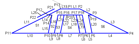
Point, Link, and Shape Codes
The following table lists the point, link, and shape codes for this subassembly that have codes assigned to them. Point, link, or shape codes for this subassembly that do not have codes assigned are not included in this table.
|
Point, Link, or Shape |
Code |
Description |
|---|---|---|
| P1 | TopCenter | Top center of the dam |
| P2 | TopRight | Top right of the dam |
| P3-P12 | Dam | Dam |
| P13 | TopLeft | Top left of the dam |
| L4-L10 | Datum | |
| S1 | Rockfill | |
| S2 | TransitionMaterial | |
| S3, S5 | FilterMaterial | |
| S4 | Core | |
| S6 | Rockfill |
Coding Diagram