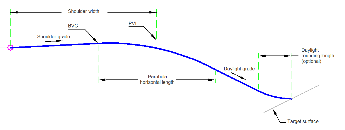
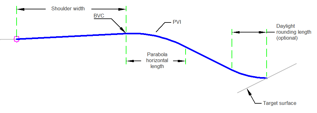
The ShoulderParabolicDaylight subassembly provides rounding at the Point of Vertical Intersection (PVI) between the shoulder and daylight links as well as fillet rounding between the daylight link and target surface.
In addition, you have the option to either define the shoulder width dimension from the origin to the PVI or from the origin to the BVC (Beginning of Vertical Curvature).
Origin to PVI Case:
Origin to BVC Case:
Attachment
The attachment point is at the inside edge of the paved shoulder, which is typically at the outside edge-of-traveled way.
Input Parameters
|
Parameter |
Description |
Type |
Default |
|---|---|---|---|
| Side | Specifies which side to place the subassembly. | Left/Right | Right |
| Shoulder Width | Width from the attachment point to the shoulder hinge point. | Numeric, positive |
10 ft 3 m |
| Shoulder Width Definition | Width of shoulder is measured from application point to this location. | PVI/BVC | PVI |
| Daylight Rounding Length (Optional) | Specifies value for length. | Numeric, positive |
5 ft 1.5 m |
| Parabola Horizontal Length | Length of the parabola at the PVI or BVC. | Numeric, positive |
8 ft 2.5 m |
| Daylight Grade (+/- for cut/fill) | The +/- % grade of the daylight slope. | Numeric | 50 ( % ) |
| Shoulder Grade | The +/- % grade of the shoulder. | Numeric | 5 ( % ) |
Target Parameters
This section lists the parameters in this subassembly that can be mapped to one or more target objects. For more information, see To Specify Corridor Targets.
|
Parameter |
Description |
Status |
|---|---|---|
| Daylight Surface | Name of the daylighting surface. The following object types can be used as targets for specifying the surface: surfaces. | Optional |
Runtime Logical Assignments
None.
Output Parameters
None.
Behavior
The subassembly builds the shape for a shoulder. The subassembly calculates the shape by using the PVI or BVC. The subassembly then checks to ensure there is sufficient space for the daylight rounding.
If there is not enough room for the daylight rounding then the length of the curve is adjusted to provide adequate length for daylight rounding.
It then checks whether parabola grade in and parabola grade out are the same value. If the same grade is found a link is drawn. If they are not the same, then either a sag or crest parabola curve is created. If applicable, a point is added for either the high point or low point on the parabolic curve.
Layout Mode Operation
In layout mode the subassembly displays the links comprising the shoulder.
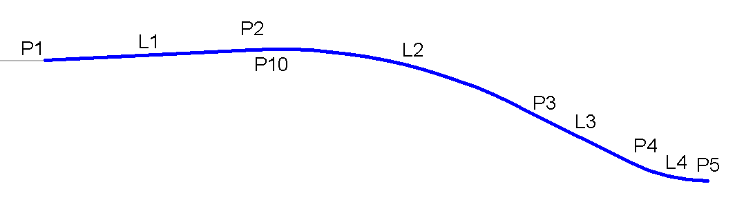
Point, Link, and Shape Codes
The following table lists the point, link, and shape codes for this subassembly that have codes assigned to them. Point, link, or shape codes for this subassembly that do not have codes assigned are not included in this table.
|
Point, Link, or Shape |
Code |
Description |
|---|---|---|
| P2 - P5 | Top | |
| L1 - L4 | Top |
Coding Diagram