The ChannelDrain subassembly inserts points and links to create a channel drain to collect water along a travelled way.
Attachment
The attachment point is at the inside edge of the channel drain. This component can be attached to either the left or right side.
Input Parameters
|
Parameter |
Description |
Type |
Default |
|---|---|---|---|
| Side | Specifies which side to place the subassembly. | Left / Right | Right |
Target Parameters
This section lists the parameters in this subassembly that can be mapped to one or more target objects. For more information, see To Specify Corridor Targets.
|
Parameter |
Description |
Status |
|---|---|---|
| Elevation | May be used to override the pipe invert. The following object types can be used as targets for specifying the elevation: profiles, 3D polylines, feature lines, or survey figures. | Optional |
Runtime Logical Assignments
None.
Output Parameters
None.
Behavior
The initial point is set at the attachment point. The points and links are then created based on the values stored within the subassembly.
Layout Mode Operation
In layout mode, this subassembly draws the subassembly.
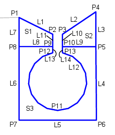
Point, Link, and Shape Codes
The following table lists the point, link, and shape codes for this subassembly that have codes assigned to them. Point, link, or shape codes for this subassembly that do not have codes assigned are not included in this table.
|
Point, Link, or Shape |
Code |
Description |
|---|---|---|
| P1-P4, P9, P10 | Concrete | Concrete corners of inlet |
| P5, P8 | ConcBottom | Bottom corner of concrete |
| P6, P7 | Slurry | Slurry |
| P11-P13 | Pipe | Pipe points |
| L1, L2 | Concrete, Top | Top of concrete |
| L3, L7, L10, L11 | Concrete | Concrete of inlet |
| L5 | Slurry | Pipe slurry |
| L12-L14 | Pipe | Pipe links |
| S1, S2 | Concrete | Inlet Concrete |
| S3 | Slurry | Slurry around pipe |
Coding Diagram