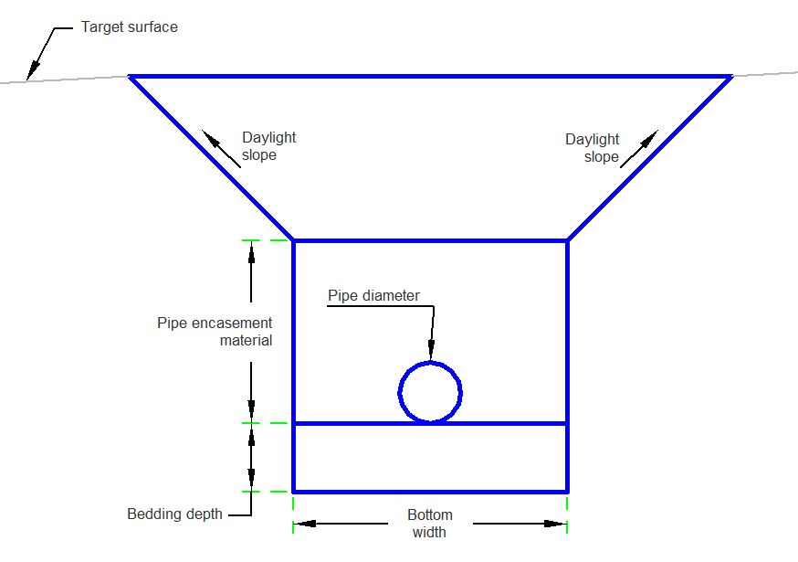
The PipeTrenchMultipleLayers subassembly has a single pipe in a trench and a layer of material encasing the pipe.
This subassembly allows volume calculation of bedding base, pipe zone, and granular backfill. The pipe is encased in a layer of material right above the bedding. The center of the pipe will have a design profile. The depth will vary in the section of granular backfill; the others will be a constant. All of the depths, widths, and diameters will change from trench to trench. The depth of the trench will vary along the alignment since it is measured from the bottom of the trench to the target surface.
Attachment
By default, the attachment point is the center of the pipe.
Input Parameters
|
Parameter |
Description |
Type |
Default |
|---|---|---|---|
| Bottom Width | Bottom width of the pipe trench. | Numeric, positive |
3 ft 1 m |
| Pipe Diameter | Pipe diameter. | Numeric, positive |
0.667 ft 0.2 m |
| Bedding Depth | Depth of the pipe bedding under the pipe invert. | Numeric, positive |
0.75 ft 0.2 m |
| Pipe Encasement Material Depth | Depth of pipe bedding over the pipe invert. | Numeric, positive |
2 ft 0.6 m |
| Target Surface Slope | X : 1 slope of the trench sideslopes. | Numeric, positive |
1 (: 1) |
Target Parameters
This section lists the parameters in this subassembly that can be mapped to one or more target objects. For more information, see To Specify Corridor Targets.
|
Parameter |
Description |
Status |
|---|---|---|
| Daylight Surface | Name of the daylighting surface. The following object types can be used as targets for specifying the surface: surfaces. | Required |
Runtime Logical Assignments
None.
Output Parameters
None.
Behavior
The elevation of the bottom of the trench is calculated as the profile grade line elevation minus half the pipe diameter plus the bedding depth. The horizontal trench bottom link is placed symmetrically about the attachment point offset at that elevation. The pipe encasement material depth is used to provide for the material around the pipe. The side slopes are extended upward to the existing surface. The horizontal bedding link is placed at the given depth above the trench bottom.
Layout Mode Operation
In layout mode, this subassembly draws a trench.
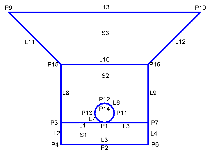
Point, Link, and Shape Codes
The following table lists the point, link, and shape codes for this subassembly that have codes assigned to them. Point, link, or shape codes for this subassembly that do not have codes assigned are not included in this table.
|
Point, Link, or Shape |
Code |
Description |
|---|---|---|
| P1 | PipeBottom | Bottom of pipe |
| P2 | BeddingBottomCenter | Center of bedding bottom |
| P3 | PipeBackfillBottom_In | Inside pipe backfill bottom |
| P4 | PipeBeddingBottom_In | Inside pipe bedding bottom |
| P6 | PipeBeddingBottom, Datum | Pipe bedding bottom |
| P7 | PipeBackfillBottom_Out | Outside pipe backfill bottom |
| P8 | PipeCenter | Center of pipe |
| P11 | Pipe | |
| P12 | PipeTop | Top of pipe |
| P13 | Pipe | |
| P15 | TopBackfill_In | Inside top of backfill |
| P16 | TopBackfill_Out | Outside top of backfill |
| P17 | Hinge, Top | |
| P18 | Top | |
| L1, L5 | PipeBackfillBottom | Pipe backfill bottom |
| L2, L4 | PipeBedding | Pipe bedding |
| L3 | PipeBeddingBottom, Datum | Pipe bedding bottom |
| L6 - L7 | Pipe | |
| L8 - L9 | Backfill | |
| L10 | TopBackfill | Top of backfill |
| L11 | TrenchSlopeInner | Inner trench slope |
| L12 | TrenchSlopeOuter | Outer trench slope |
| L13 | TrenchTop, Top | Top of trench |
| S1 | PipeBedding | Pipe bedding |
| S2 | PipeBackfillMaterial | Pipe backfill material |
| S3 | TrenchMaterial | Trench material |
Coding Diagram