The GabionWall subassembly creates a Gabion Wall. The Gabion Wall is based on Caltrans Standard Plan D100A.
You should verify that the dimensions used match your interpretation of the standard plan.
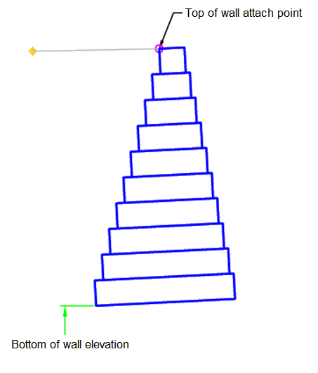
Case: Attachment at Top of Wall
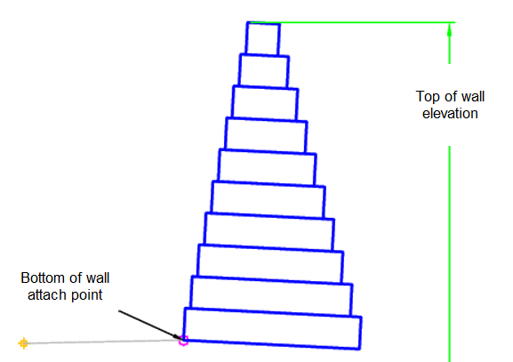
Case: Attachment at Bottom of Wall
Attachment
The attachment point is at the inside edge of the initial cut or fill slope. This component can be attached to either the left or right side.
Input Parameters
|
Parameter |
Description |
Type |
Default |
|---|---|---|---|
| Side | Specifies which side to place the subassembly | Left / Right | Right |
| Stepped Offset Distance | Face offset distance for gabions | Numeric, positive |
0.5 ft 0.15 m |
| Has Surcharge | Has soil above the wall | Yes / No | No |
| Gabion Grade | Grade of gabion | Numeric | 5 (%) |
| Attachment Place | Attachment place on wall | TopOfWall / BottomOfWall | Bottom Of Wall |
Target Parameters
This section lists the parameters in this subassembly that can be mapped to one or more target objects. For more information, see To Specify Corridor Targets.
|
Parameter |
Description |
Status |
|---|---|---|
| Top of Wall Elevation | May be used to set the top of wall elevation when the attachment point is set to bottom of wall. The following object types can be used as targets for specifying the elevation: profiles, 3D polylines, feature lines, or survey figures. | Required when attachment point is Bottom of Wall |
| Bottom of Wall Elevation | May be used to set the bottom of wall elevation when the attachment point is set to top of wall. The following object types can be used as targets for specifying the width: alignments, polylines, feature lines, or survey figures. | Required when attachment point is Top of Wall |
Runtime Logical Assignments
The dimensions of the gabion layers are set within the subassembly based on the current layer and the height of the gabion wall.
Output Parameters
None.
Behavior
The initial hinge point is set at the attachment point. The gabion wall height is then calculated from the attachment point and the top of wall or bottom of wall profile. The maximum number of gabion layers is 10 and is split up into 3 ft (1 m) layers. Gabion wall height is rounded up to an even number of layers.
Each gabion layer is then built based on the input parameters.
Layout Mode Operation
In layout mode, this subassembly draws the maximum 10 gabion layers.
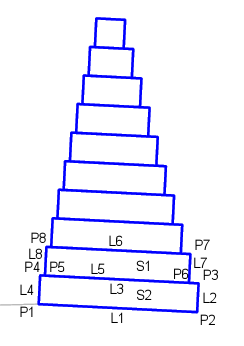
Point, Link, and Shape Codes
The following table lists the point, link, and shape codes for this subassembly that have codes assigned to them. Point, link, or shape codes for this subassembly that do not have codes assigned are not included in this table.
|
Point, Link, or Shape |
Code |
Description |
|---|---|---|
| P1-PX | Gabion | Gabion point, applied to all points |
| L1, L5 | Datum | Repeats for each layer |
| L3, L6 | Top | Repeats for each layer |
| SX | GabionX | X is replaced by the current gabion layer |
Coding Diagram
The first two gabion layers are labeled in the following illustration. The other gabion layers are similar.