The SoundWall subassembly inserts links and shapes to create a sound wall based on Caltrans Standard Plan B15-1.
You should verify that the dimensions used match your interpretation of the standard plan.
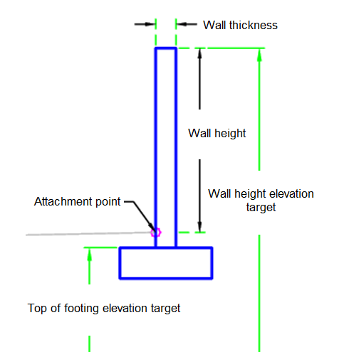
Spread Footing:
Trench Footing:
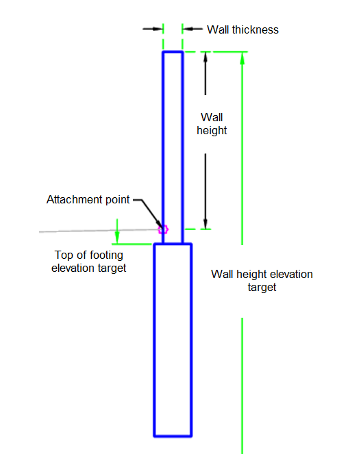
Attachment
The attachment point is at the inside edge of the sound wall. This component can be attached to either the left or right side.
Input Parameters
|
Parameter |
Description |
Type |
Default |
|---|---|---|---|
| Side | Specifies which side to place the subassembly | Left / Right | Right |
| Footing Shape | Footing shape to use | Spread Footing / Trench Footing | Trench Footing |
| Footing Case | Footing case | Case 1 / Case 2 | Case 2 |
| Wall Height | Wall height above attachment point | Numeric, positive |
6 ft 2 m |
| Wall Thickness | Wall thickness | Numeric |
0.66 ft 0.20 m |
| Soil Strength | Strength of the soil | Soil 25 / Soil 30 / Soil 35 | Soil 30 |
Target Parameters
This section lists the parameters in this subassembly that can be mapped to one or more target objects. For more information, see To Specify Corridor Targets.
|
Parameter |
Description |
Status |
|---|---|---|
| Wall Height | May be used to override the wall height tie the elevation of the top of wall to the elevation of a profile. The following object types can be used as targets for specifying the elevation: profiles, 3D polylines, feature lines, or survey figures. | Optional |
| Top of Footing | May be used to override the top of footing and tie the elevation of the top of footing to the elevation of a profile. The following object types can be used as targets for specifying the elevation: profiles, 3D polylines, feature lines, or survey figures. | Optional |
Runtime Logical Assignments
The dimensions of the sound wall footing is found within the subassembly based on the input parameters.
Output Parameters
None.
Behavior
The initial point is set at the attachment point. The dimensions of the footings are determined by the input parameters. The wall points, links, and shapes are built and then the footing is built.
Layout Mode Operation
In layout mode, this subassembly draws the sound wall based on the input parameters.
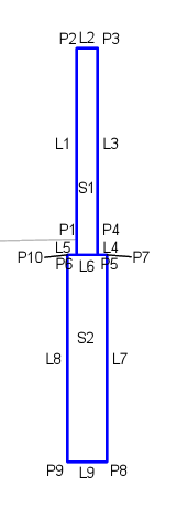
Point, Link, and Shape Codes
The following table lists the point, link, and shape codes for this subassembly that have codes assigned to them. Point, link, or shape codes for this subassembly that do not have codes assigned are not included in this table.
|
Point, Link, or Shape |
Code |
Description |
|---|---|---|
| P1, P4 | W_Hinge | Wall hinge point |
| P2 | W_Front | Front of wall |
| P3 | W_Back | Back of wall |
| P7 | W_Outside | Footing outside corner |
| P10 | W_Inside | Footing inside corner |
| L1-L3 | Top, Wall | Top of wall |
| L4-L5 | Wall | Wall surface |
| L9 | Footing_Bottom | |
| S1 | Wall | |
| S2 | Footing |
Coding Diagram
Spread Footing:
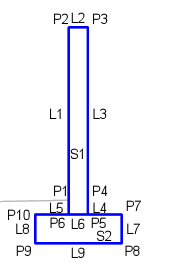
Trench Footing: