The CaltransB3RetainingWall subassembly inserts links to create a retaining wall based on Caltrans Standard Plan B3-3 Retaining Wall.
You should verify that the dimensions used match your interpretation of the standard plan.
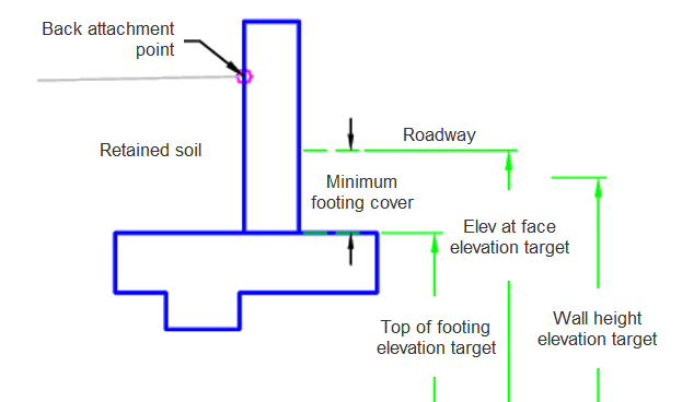
Case 1: Attachment point at back of retaining wall
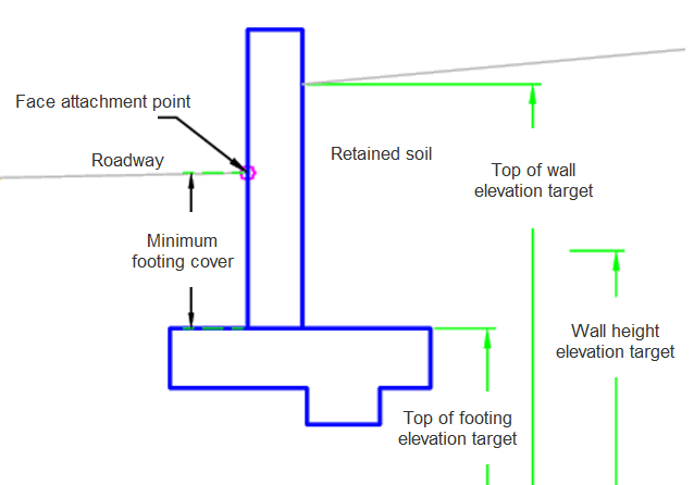
Case 2: Attachment point at face of wall
Attachment
The attachment is set at either the back of the retaining wall or the front.
Input Parameters
|
Parameter |
Description |
Type |
Default |
|---|---|---|---|
| Side | Specifies which side to place the subassembly. | Left / Right | Right |
| Wall Link Codes | The code which is applied to the links that makes up the wall. | Text | Wall |
| Wall Point Codes | The code which is applied to the points that makes up the wall. | Text | Wall |
| Footing Point Codes | The code which is applied to the points that makes up the footing. | Text | Footing |
| Footing Link Codes | The code which is applied to the links that make up the footing. | Text | Footing |
| Minimum Footing Cover | For Back facing, this parameter determines the height above the footing if no Elev At Face elevation target is set. | Numeric, positive |
1.5 ft 0.45 m |
| Attachment Point | Specifies if the attachment point is on the face of the retaining wall or the back of the retaining wall. | Face / Back | Back |
Target Parameters
This section lists the parameters in this subassembly that can be mapped to one or more target objects. For more information, see To Specify Corridor Targets.
|
Parameter |
Description |
Status |
|---|---|---|
| Wall Height | Used to control the height dimensions used to build the retaining wall. The following object types can be used as targets for specifying the elevation: profiles, 3D polylines, feature lines, or survey figures. | Required |
| Top of Footing | May be used to control the top of footing elevation. The following object types can be used as targets for specifying the elevation: profiles, 3D polylines, feature lines, or survey figures. | Required |
| Top of Wall | May be used to override the top of wall elevation when the Attachment Point is Face. The following object types can be used as targets for specifying the elevation: profiles, 3D polylines, feature lines, or survey figures. | Optional |
| Elev at Face | May be used to control an elevation point at the face of wall when the Attachment Point is Back. The following object types can be used as targets for specifying the elevation: profiles, 3D polylines, feature lines, or survey figures. | Optional |
Runtime Logical Assignments
Retaining wall dimensions derive from the Caltrans Standard Plans values for a B-3 Retaining Wall.
Output Parameters
None.
Behavior
The initial hinge point is set at the attachment point.
The Wall Height profile is checked to see if it exists. If the profile does not exist an error message is provided. If the Wall Height Profile is not found then the dimensions for a 1 ft (0.3 m) wall is assumed. The Wall Height Profile is set to a truncated value of the elevation.
Case 1: Attachment point at back of retaining wall
If the Elev at Face target is set the elevation is used. If the Elev at Face is not set then the Top of Footing plus the minimum footing cover is used. The top of footing target elevation is used to determine the physical height of the retaining wall. The footing builds using the standard plan dimensions based on the Wall Height Target.
Case 2: Attachment point at face of wall
The calculation for the top of wall is performed based on the Top Wall Target. The footing elevation is based on the Top of Footing Target. If the Top of Footing Target is not found then the Minimum Footing cover is used below the Attachment Point. The footing builds using the standard plan dimensions based on the Wall Height Target.
Layout Mode Operation
In layout mode, this subassembly draws the retaining wall based on a wall height of 1 ft (0.3 m).
Point, Link, and Shape Codes
The following table lists the point, link, and shape codes for this subassembly that have codes assigned to them. Point, link, or shape codes for this subassembly that do not have codes assigned are not included in this table.
|
Point, Link, or Shape |
Code |
Description |
|---|---|---|
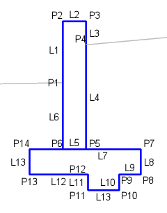
| P1 | Wall, AttachPoint | The attachment point of the retaining wall |
| P2-P4, P13 | Wall | |
| P5-P12 | Footing | |
| L1-L6 | Wall | |
| L7-L13 | Footing | |
| S1 | Wall | |
| S2 | Footing |
Coding Diagram
Case 1: Attachment point at back of retaining wall
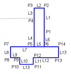
Case 2: Attachment point at face of wall