The ReinforcedConcreteCribWall subassembly inserts links to create a Reinforced Concrete Crib Wall Based on Caltrans Standard Plan C7A.
You should verify that the dimensions used match your interpretation of the standard plan.
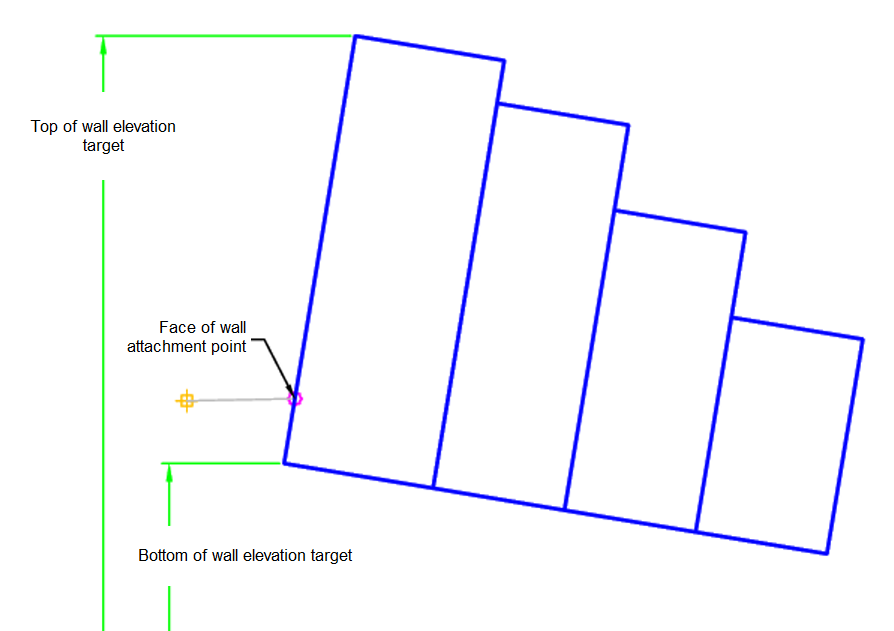
Case: Face of Wall
Case: Top of Wall
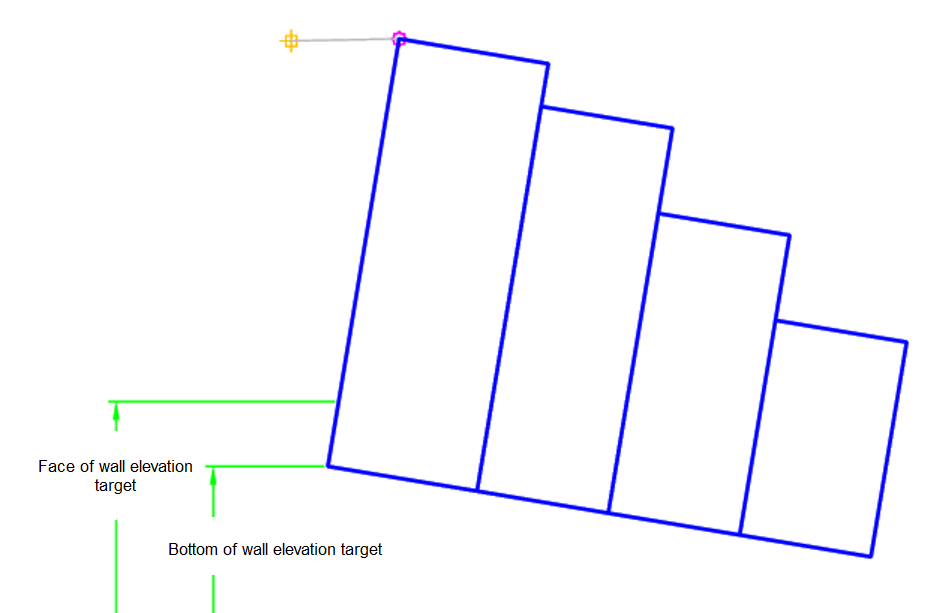
Attachment
The attachment point is at the inside edge of the initial cut or fill slope. This component can be attached to either the left or right side.
Input Parameters
|
Parameter |
Description |
Type |
Default |
|---|---|---|---|
| Side | Specifies which side to place the subassembly | Left / Right | Right |
| Batter of Wall | Batter of wall | Vertical / B 1:6 / B 1:4 | B 1:6 |
| Load Case | Load case | Flat / Embankment | Flat |
| Wall Type | Wall type | Type A / Type B / Type C | Type C |
| Attach Point | Attach point | Top of Wall / Face of Wall | Face of Wall |
Target Parameters
This section lists the parameters in this subassembly that can be mapped to one or more target objects. For more information, see To Specify Corridor Targets.
|
Parameter |
Description |
Status |
|---|---|---|
| Bottom of Wall | May be used to set the bottom of wall elevation. The following object types can be used as targets for specifying the elevation: profiles, 3D polylines, feature lines, or survey figures. | Optional |
| Face of Wall | May be used to set the face of wall elevation point. The following object types can be used as targets for specifying the elevation: profiles, 3D polylines, feature lines, or survey figures. | Optional (Attachment Point = Top of Wall) |
| Top of Wall | May be used to set the top of wall elevation. The following object types can be used as targets for specifying the elevation: profiles, 3D polylines, feature lines, or survey figures. | Optional (Attachment Point = Face of Wall) |
Runtime Logical Assignments
The dimensions of the wall are set from the input parameters and the saved values of the Caltrans Standard Plan C7A.
Output Parameters
None.
Behavior
The initial hinge point is set at the attachment point. The dimensions of the walls are then set by the runtime logical assignments based on the input parameters. The shape is then built.
Layout Mode Operation
In layout mode, this subassembly draws reinforced concrete crib wall based on the input parameters.
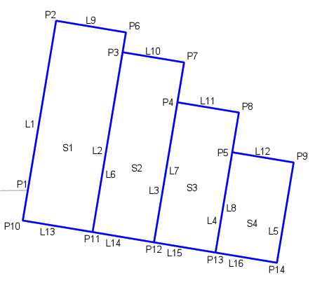
Point, Link, and Shape Codes
The following table lists the point, link, and shape codes for this subassembly that have codes assigned to them. Point, link, or shape codes for this subassembly that do not have codes assigned are not included in this table.
|
Point, Link, or Shape |
Code |
Description |
|---|---|---|
| P1 | WallFace | Face of wall |
| P2-P9 | Top | |
| P10-P14 | Bottom | |
| L1, L9-L12 | Top | |
| L13-L16 | Datum | |
| S1-S4 | Concrete |
Coding Diagram