The LaneWithMarkedPoint subassembly creates a cross-sectional representation of a travel lane, with a way to connect a link from the attachment point to a previously named marked point.
This subassembly can be used in a variety of situations, including connecting between adjacent roadways where the relative offsets and elevations vary, or across a gore area between converging roadways. Use the MarkPoint subassembly if the connecting point has not already been named.
Attachment
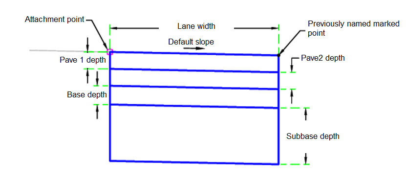
The attachment point is at the beginning of the lane. The link may go in any direction. The direction is determined by the location of the marked point relative to the attachment point. Be sure to name the marked point and set the marked point name in this subassembly. The Marked Point name must be in all UPPER CASE letters.
Input Parameters
|
Parameter |
Description |
Type |
Default |
|---|---|---|---|
| Side | Specifies which side to place the subassembly | Left / Right | Right |
| Insertion Point | Specifies insertion point of the lane either at the crown, or at the edge of travel way | Crown / EdgeOfTravelWay | Crown |
| Crown Point on Inside | Specifies that inside edge of travel way be coded as Crown | Yes / No | Yes |
| Lane Width | Width of the lane from the offset of the inside edge to the offset of the outside edge | Numeric, positive |
12 ft 3.6 m |
| Base Depth | Depth of base | Numeric, positive |
0.33 ft 0.10 m |
| Default Slope | Default slope of the lane to be used when the superelevation slope for the alignment is not defined | Numeric | -2% |
| Pave1 Depth | Thickness of the Pave1 layer (zero to omit) | Numeric, positive |
0.083 ft 0.025 m |
| Pave2 Depth | Thickness of the Pave2 layer (zero to omit) | Numeric, positive |
0.33 ft 0.10 m |
| Subbase Depth | Thickness of the subbase layer (zero to omit) | Numeric, positive |
1 ft 0.30 m |
| Mark Point Name | Mark Point Name, use UPPER CASE | String | MARKPOINT |
Target Parameters
This section lists the parameters in this subassembly that can be mapped to one or more target objects. For more information, see To Specify Corridor Targets.
None.
Runtime Logical Assignments
None.
Output Parameters
|
Parameter |
Description |
Type |
|---|---|---|
| Lane Width | Width of the lane | Numeric, positive |
| LaneSlope | % slope of the lane | Numeric |
Behavior
The marked point is found and the lane width and lane slope are calculated based on the marked point location. If the marked point is not found, the entered lane width and lane slope from the user input values are used.
Starting at the attachment point, a finish grade surface and parallel subgrade are inserted using the given width, depth, and the found or entered slope. Vertical links close the shape at either end of the lane.
Layout Mode Operation
In layout mode, this subassembly displays all lane links using the width and depth input parameters.
Point, Link, and Shape Codes
The following table lists the point, link, and shape codes for this subassembly that have codes assigned to them. Point, link, or shape codes for this subassembly that do not have codes assigned are not included in this table.
|
Point, Link, or Shape |
Code |
Description |
|---|---|---|
| P1 | Crown | Crown point on finish grade (optional) |
| P2 | ETW | Inside edge of lane on finish grade |
| P3 | Crown_Pave1 | Crown point on the Pave1 layer (optional) |
| P4 | ETW_Pave1 | Inside edge of lane on Pave |
| P5 | Crown_Pave2 | Crown point on the Pave2 layer (optional) |
| P6 | ETW_Pave2 | Inside edge of lane on Pave2 |
| P7 | Crown_Base | Crown point on base grade (optional) |
| P8 | ETW_Base | Inside edge of lane on Base |
| P9 | Crown_Sub | Crown point on subbase grade (optional) |
| P10 | ETW_Sub | Inside edge of lane on Subbase |
| L1 | Top, Pave | Finish grade surface |
| L2 | Pave1 | Pave1 surface |
| L3 | Pave2 | Pave2 surface |
| L4 | Base | Base surface |
| L5 | SubBase, Datum | Subbase surface |
| S1 | Pave1 | Area between finish grade and Pave1 |
| S2 | Pave2 | Area between Pave1 and Pave2 |
| S3 | Base | Area between Pave2 and Base |
| S4 | SubBase | Area between Base and Subbase |
Coding Diagram
