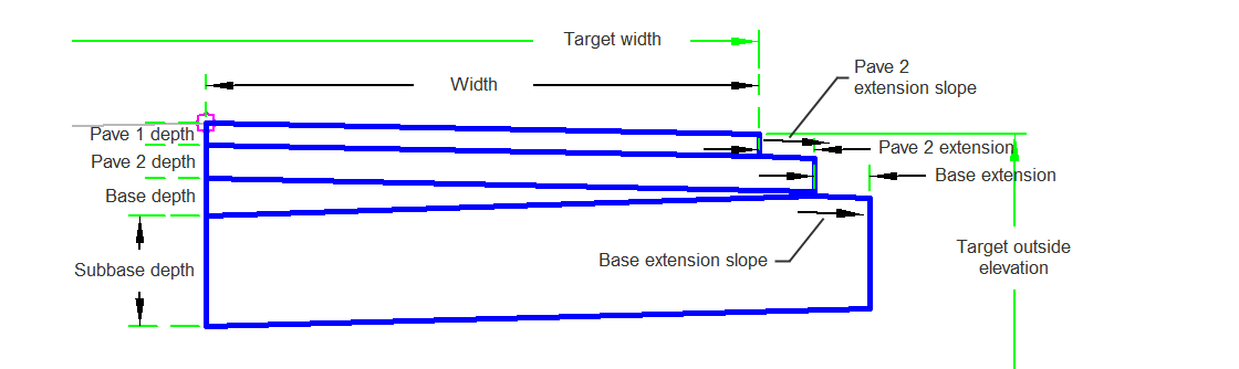
The ShoulderVariesExtensions subassembly has a base and subbase that extends past the rest of the pavement layers.
Attachment
The attachment point is at the inside edge of the paved shoulder, which is typically at the outside edge-of-traveled way.
Input Parameters
|
Parameter |
Description |
Type |
Default |
|---|---|---|---|
| Side | Specifies which side to place the subassembly. | Left/Right | Right |
| Insertion Point | Specifies insertion point of the lane either at the crown, or at the edge of travel way. | Crown/ EdgeOfTravelWay | Crown |
| Crown Point on Inside | Specifies that inside edge of travelway be coded as Crown. | Yes/No | No |
| Width | Width of the lane from the offset of the inside edge to the offset of the outside edge. | Numeric, positive |
12 ft 3.5 m |
| Base Depth | Depth of base course. | Numeric, positive |
0.33 ft 0.1 m |
| Default Slope | Default slope of the lane to be used when the superelevation slope for the alignment is not defined. | Numeric | -2.00 ( % ) |
| Pave1 Depth | Thickness of the Pave1 layer (zero to omit). | Numeric, non-negative |
0.083 ft 0.025 m |
| Pave2 Depth | Thickness of the Pave2 layer (zero to omit). | Numeric, non-negative |
0.083 ft 0.025 m |
| Subbase Depth | Thickness of the subbase layer (zero to omit). | Numeric, non-negative |
1 ft 0.3 m |
| Pave2 Extension | Extension Beyond Pave1. | Numeric, non-negative |
0.5 ft 0.15 m |
| Base Extension Slope | % slope of the base extension. | Numeric | -2.00 ( % ) |
| Base Extension | Extension Beyond Pave2. | Numeric, non-negative |
0.5 ft 0.15 m |
| Pave2 Extension Slope | % slope of the Pave2 extension. | Numeric | -2.00 ( % ) |
Target Parameters
This section lists the parameters in this subassembly that can be mapped to one or more target objects. For more information, see To Specify Corridor Targets.
|
Parameter |
Description |
Status |
|---|---|---|
| Target Outside Elevation | May be used to override the shoulder slope and the outside shoulder edge to the elevation of a profile. The following object types can be used as targets for specifying this elevation: profiles, 3D polylines, feature lines, or survey figures. | Optional |
| Target Width | May be used to override the shoulder width and tie the shoulder width to an offset alignment. The following object types can be used as targets for specifying the offset: alignments, polylines, feature lines, or survey figures. | Optional |
Runtime Logical Assignments
None.
Output Parameters
|
Parameter |
Description |
Type |
|---|---|---|
| Lane Width | Width of the lane | Numeric |
| Lane Slope | % slope of the lane | Numeric |
Behavior
The finish grade of the shoulder is inserted for the given Shoulder Width and Default Shoulder Slope outward from the attachment point. The Pave2 points and links are then drawn. A Pave2 extension is provided using the input parameters. The Base points and links, including extension, are calculated using the input parameters. The Subbase points, links, and shape, including extension, are calculated using the input parameters.
Layout Mode Operation
In layout mode the subassembly displays the links comprising the shoulder.
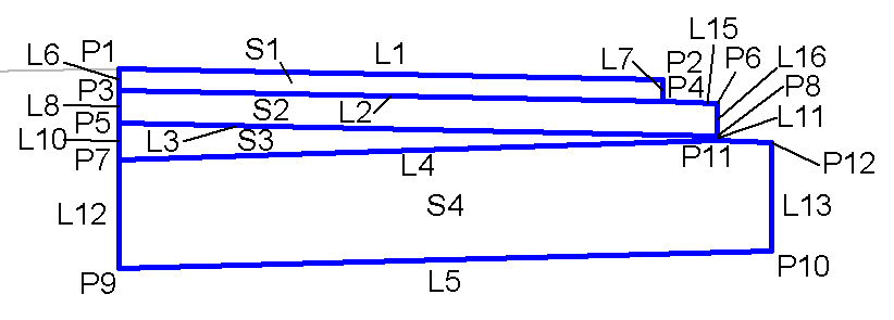
Point, Link, and Shape Codes
The following table lists the point, link, and shape codes for this subassembly that have codes assigned to them. Point, link, or shape codes for this subassembly that do not have codes assigned are not included in this table.
|
Point, Link, or Shape |
Code |
Description |
|---|---|---|
| P1 | Top, Hinge | |
| P4 | Daylight, Top | |
| L1 - L3 | Top | |
| S1 | Pave1 | |
| S2 | Pave2 | |
| S3 | Base | |
| S4 | Subbase |
Coding Diagram