The ShoulderIntersectLeft subassembly creates a shoulder extended to a daylight point based on the shoulder slope and subgrade grade. It only operates to the left.
Attachment
The attachment point is at the inside edge of the left paved shoulder, which is typically at the outside edge-of-traveled way on the left side of the baseline.
Input Parameters
|
Parameter |
Description |
Type |
Default |
|---|---|---|---|
| Top Inside Point Code | A list of codes to be assigned to the top inside point. | Comma-separated string | P1 |
| Bottom Inside Point Code | A list of codes to be assigned to the bottom inside point. | Comma-separated string | P2 |
| Outside Point Code | A list of codes to be assigned to the outside point. | Comma-separated string | P3 |
| Top Link Code | A list of codes to be assigned to the top link. | Comma-separated string | L2 |
| Bottom Link Code | A list of codes to be assigned to the bottom link. | Comma-separated string | L3 |
| Depth Link Code | A list of codes to be assigned to the depth link. | Comma-separated string | L1 |
| Depth | Depth of the shoulder below the attach point. | Numeric, positive |
1.5 ft 0.45 m |
| Subgrade Grade | % slope of the subgrade. | Numeric | -4 ( % ) |
| Shoulder Slope | Slope of the shoulder. | Numeric, positive | 4 (: 1) |
| Material Shape Code | A list of codes to be assigned to the material shape. | Comma-separated string | Subbase |
| Superelevation | Specifies to use superelevation slope. | Selection list | LeftOutsideShoulder |
Target Parameters
None.
Runtime Logical Assignments
None.
Output Parameters
None.
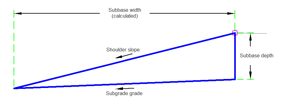
Behavior
The shoulder is inserted for the given shoulder depth, shoulder slope, and shoulder subgrade. The width is calculated where the shoulder slope and shoulder subgrade intersects. Then the points, links, and shapes are calculated.
Layout Mode Operation
In layout mode the subassembly displays the links comprising the shoulder.
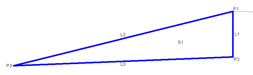
Point, Link, and Shape Codes
The following table lists the point, link, and shape codes for this subassembly that have codes assigned to them. Point, link, or shape codes for this subassembly that do not have codes assigned are not included in this table.
|
Point, Link, or Shape |
Code |
Description |
|---|---|---|
| P1 | Hinge, TopInsidePCode, Top | Top Inside Point Code |
| P2 | BottomInsidePCode | Bottom Inside Point Code |
| P3 | Daylight_Sub, OutsidePCode, Top | Daylight Subgrade, Outside Point Code |
| L1 | DepthLinkCode | Depth Link Code |
| L2 | Top, TopLinkCode | Top Link Code |
| L3 | Datum, BottomLinkCode | Bottom Link Code |
| S1 | MaterialCode | Material Code |
Coding Diagram