The ConditionalHorizontalTarget2 subassembly automatically applies various subassemblies, such as widening, curb and gutter, ditching, or daylighting, to an assembly based on whether an offset target is found at the corridor station.
The ConditionalHorizontalTarget2 is different from the ConditionalHorizontalTarget with additional parameters on the direction to search for targets and a minimum distance to find offset targets.
The ConditionalHorizontalTarget2 subassembly is a conditional subassembly, which is a special type of subassembly. Conditional subassemblies automatically add specified subassemblies to an assembly when certain conditions, which you specify, exist.
For example, when an assembly contains a ConditionalHorizontalTarget2 subassembly, AutoCAD Civil 3D analyzes the station to determine whether an offset target exists within a specified distance and the specified direction(s). The offset is set from either the current corridor baseline or the subassembly attachment point. Depending on the ConditionalHorizontalTarget2 subassembly parameters, different types of subassemblies are automatically added to the assembly.
You can add one or multiple ConditionalHorizontalTarget2 subassemblies to an assembly to create simple or complex conditional behaviors. For example you can add a set of polylines to the model that show the location of sidewalks. Because the lines stop where driveways cross the sidewalk, the conditional subassembly adds and removes the sidewalk depending on the presence of the sidewalk line. The conditional subassembly eliminates the need to apply a different assembly to the corridor where a sidewalk is not needed.
When you create an assembly using ConditionalHorizontalTarget2 subassemblies, the assembly construction displayed in the Construction tab of the Assembly Properties dialog box indicates the order in which the subassemblies are processed.
It is important to note the following when using the ConditionalHorizontalTarget2 subassembly:
- AutoCAD Civil 3D analyzes the location of the station associated with the subassembly relative to the target offset to determine whether the offset is found.
- When an assembly containing ConditionalHorizontalTarget2 subassemblies is applied to a corridor model, only specific portions of the assembly are applied to any given assembly construction.
- Since the ConditionalHorizontalTarget2 subassembly uses targets, you must set targets on any ConditionalHorizontalTarget2 subassemblies before you generate the corridor. If the targets are not set, the subassembly returns Not Found. For more information, see To Specify Corridor Targets.
- Unlike most other subassemblies, the ConditionalHorizontalTarget2 subassembly does not create any points, links, or shapes in modeling mode.
Attachment
This subassembly can be attached to any subassembly or assembly attachment point. Subsequent subassemblies can be attached to the end point of the ConditionalHorizontalTarget2 subassembly.
Input Parameters
|
Parameter |
Description |
Type |
Default |
|---|---|---|---|
| Side | Specifies which side to place the subassembly. | Left / Right | Right |
| Layout Width | Specifies the length of the line that is drawn to represent this subassembly in layout mode. This parameter, in combination with the Layout Grade parameter, enables you to position the ConditionalHorizontalTarget2 subassembly and subassemblies that are attached to it, but does not have any effect in the corridor model. | Numeric, positive |
12.0 ft 3.6 m |
| Layout Grade | Specifies the grade of the line that is drawn to represent this subassembly in layout mode. This parameter, in combination with the Layout Width parameter, enables you to position the ConditionalHorizontalTarget2 subassembly and subassemblies that are attached to it, but does not have any effect in the corridor model. | Numeric |
1:1 (found) -1:1 (not found) |
| Condition | Specifies the condition available for this subassembly. The Found condition is processed if the offset target is found within the maximum distance. The Not Found condition is processed if the offset target is not set or is not found at the station within the maximum distance. | Found / Not Found | Found |
| Maximum Distance | Specifies the maximum width within which the subassembly looks for the offset target. If the offset is not found within the specified distance, the Not Found conditional is processed. | Numeric, positive |
9999 ft 9999 m |
| Minimum Distance | Specifies the minimum width within which the subassembly looks for the offset target. If the offset is found within the specified distance, the Not Found conditional is processed. | Numeric, positive |
0 ft 0 m |
| Search Direction | Specifies where the search direction for the target. | Outward / Inward / Both Directions | Both Directions |
| Search Origin | Specifies whether the distance value is calculated from the baseline alignment or from the attachment point of the subassembly. | Baseline / Attachment Point | Baseline |
Target Parameters
This section lists the parameters in this subassembly that can be mapped to one or more target objects. For more information, see To Specify Corridor Targets.
|
Parameter |
Description |
Status |
|---|---|---|
| Offset | Alignment, feature line, survey figure or polylines. If the specified offset target is found at the station, then the Found condition is processed. | Optional (if not set, the conditional returns Not Found) |
Runtime Logical Assignments
None.
Output Parameters
None.
Behavior
See description above.
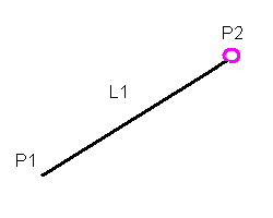
Layout Mode Operation
In layout mode, this subassembly draws a line using the Layout Width and Layout Grade input parameter values. This line represents the location in the assembly where the ConditionalHorizontalTarget2 subassembly is applied.
Point, Link, and Shape Codes
Unlike most other subassemblies, the ConditionalHorizontalTarget2 subassembly does not create any points, links, or shapes in modeling mode.
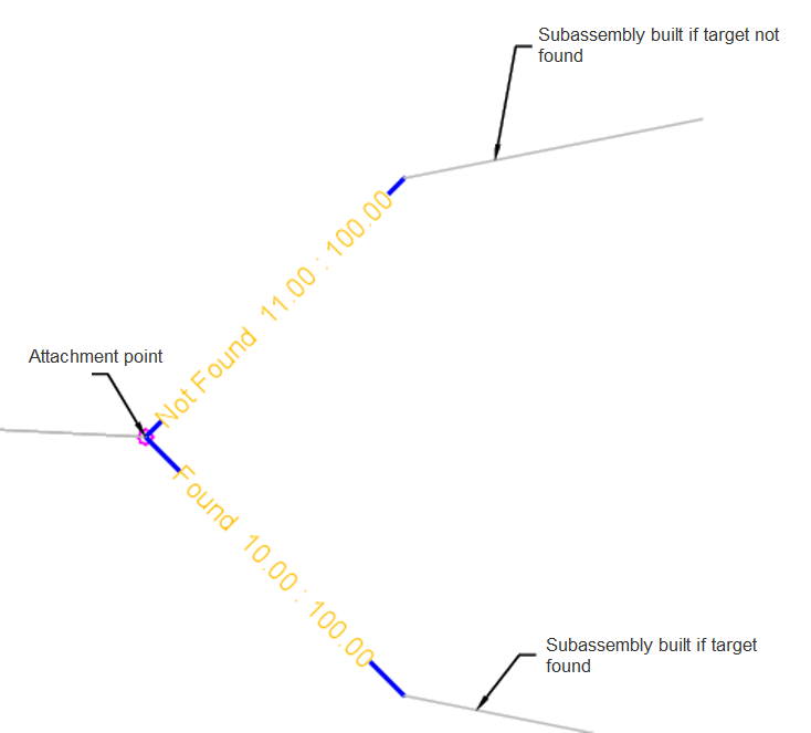
Coding Diagram
The following coding diagram shows the points and links that are created in layout mode. No point, link, or shape codes are created for this subassembly in modeling mode.