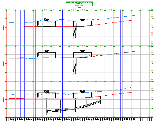
In this exercise, you will create a series of three profile views that contain a centerline and left and right offset profiles.
Stacked profile views are a collection of related profiles that are drawn in separate, vertically arranged profile views. When each profile is displayed on its own profile view grid, more space is available to annotate each profile.

This exercise continues from Exercise 5: Creating Multiple Profile Views.
Create stacked profile views
- Open
Profile-5F.dwg, which is located in the
tutorials drawings folder.
The drawing contains an existing ground surface, several alignments, and a profile view. The profile view contains centerline and left and right edge of pavement (EOP) profiles of the alignment that travels from North to South along the West side of the site. Because the profiles are crowded in the profile view, you will create a series of stacked profile views so that you can see the profiles clearly and have ample room for annotation.
- Click
tab
 panel
panel  drop-down
  Find.
Find.
- In the
Create Profile View wizard, on the
General page, specify the following parameters:
- Select Alignment: North-South Road
- Show Offset Profiles By Vertically Stacking Profile Views:
Selected
The graphic at the bottom of the page changes color to indicate that the option is active.
Note:The Profile View Style setting on this page is not used. You will assign separate styles for each profile view in the stack.
- On the left side of the Create Profile View wizard, click Stacked Profile.
- On the
Stacked Profile page, specify the following parameters:
- Number Of Stacked Views: 3
- Gap Between Views:
0
Note:
The Gap Between Views value is measured in drawing units. A positive value adds space between the profile view grids. A negative value causes the profile view grids to overlap.
- Top View Style: Stacked - Top
- Middle View Style: Stacked - Middle
- Bottom View Style: Stacked - Bottom
- Click Next.
- On the
Profile Display Options page, in the
Select Stacked View To Specify Options For list, select
Middle View.
Note:
The number of views that is visible in this list depends on the value you specified for Number Of Stacked Views in Step 5.
- In the
Specify Profile Display Options table, select the
Draw check box for the following profiles:
- EG Centerline
- Centerline
- In the Select Stacked View To Specify Options For list, select Top View.
- In the
Specify Profile Display Options table, select the
Draw check box for the following profiles:
- EG Left Offset
- EOP Left
- In the Select Stacked View To Specify Options For list, select Bottom View.
- In the
Specify Profile Display Options table, select the
Draw check box for the following profiles:
- EG Right Offset
- EOP Right
- Click Next.
- On the
Pipe Network Display page, in the
Select Stacked View To Specify Options For list, select
Bottom View.
Most of the pipe network is on the right-hand side of the alignment. You will specify that the pipe network components will be displayed in the profile view that displays the right EOP profiles.
- In the Select Pipe Networks To Draw In Profile View area, select the Select check box.
- In the Name column, expand the Network - (1) pipe network.
- Clear the check boxes for the following parts:
- W-E Pipe - (1)
- W-E Pipe - (2)
- W-E Structure - (1)
- W-E Structure - (2)
These parts are a branch of the pipe network that follow the West-East alignment.
- In the Select Stacked View To Specify Options For list, select Middle View.
- In the Select Pipe Networks To Draw In Profile View list, select the Select check box.
- Clear all check boxes except for the following parts:
- W-E Pipe - (1)
- W-E Pipe - (2)
- W-E Structure - (1)
- W-E Structure - (2)
- In the Select Stacked View To Specify Options For list, select Top View.
- In the Select Pipe Networks To Draw In Profile View list, select the Select check box.
- Clear all check boxes except for the following parts:
- W-E Pipe - (1)
- W-E Pipe - (2)
- W-E Structure - (1)
- W-E Structure - (2)
- Click Create Profile View.
- In the drawing, pan to the clear area at the right of the surface. Click to place the profile views.
- In
Toolspace, on the
Prospector tab, expand the
Alignments
 Road: North-South
 Profile Views collection.
Notice that three separate profile views were created.
To continue to the next tutorial, go to Tutorial: Working with Data Bands.