In this exercise, you will build the top portion of the vault. This is a rectangular frame with a rectangular opening. You will build this portion with dimensions that can be modified from within Autodesk Civil 3D when the part is in use.
This exercise continues from Exercise 1: Defining the New Part in the Structure Catalog.
- Expand Modeling
 Work Planes, right-click Rim
 Set View. The current view and UCS is set to match the work plane.
 - Right-click Rim
 Add Profile
 Rectangular. Click two points to draw a rectangle in the drawing area. A rectangular profile object is shown in the drawing.
 - Expand Rim, right-click Rectangular Profile in the Content Builder window and then click Rename. Enter Frame Outer Edge as the name. This name makes it easier to identify the component.
- Repeat these steps to create another rectangular profile within the first one. Name it Frame Opening.
Next you will establish some construction geometry and constraints to keep the opening positioned at the center of the box. Rectangular profiles representing the outer edge of the frame and the opening have been created.
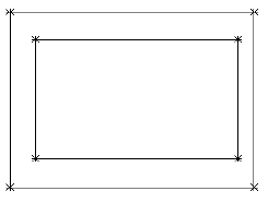
- Right-click Rim
 Add Geometry
 Point. Click a location near the center of the rectangles. Press ESC. This becomes the center point of the structure.
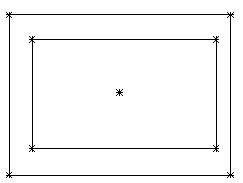
- Expand the Geometry folder. Right-click Point 2D
 Rename. Enter Fixed Center for the name. This name makes it easier to identify the component.
 - Right-click Fixed Center
 Fixed. The point is now fixed. Constraints that include this point will not move the point.
 - Right-click Rim
 Add Constraints
 Equal Distance. Click the point at the top left corner of the outer rectangle, then the Fixed Center Point. For the second pair, click the point at the bottom right corner of the outer rectangle, and the Fixed Center Point.
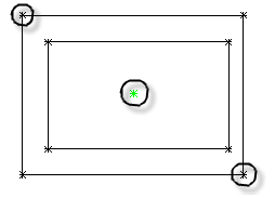
- Repeat this step for the bottom left and upper right corners of the outer rectangle. This constrains the outer rectangle so that it is centered about the Fixed Center.
- Repeat these steps for the four corners of the inner rectangle. Both rectangles are now centered about the fixed point.
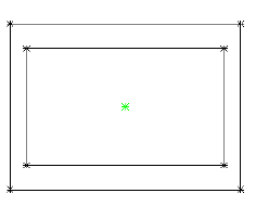
- Right-click Rim
 Add Constraints
 Parallel. Click any line on the outer rectangle, then the line that is parallel to it on the inner rectangle. This constraint prevents the inner rectangle from rotating within the outer rectangle.
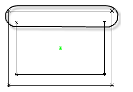
- Right-click Rim
 Add Dimension
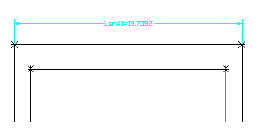
 Distance. Click two points at either end of the top side of the outer rectangle.
 Click a point to set the location of the dimension. A dimension named LenA1 is created for the long side of the outer edge of the frame.
- Repeat these steps for the right side of the outer rectangle.
A dimension named LenA2 is created for the short side of the outer edge of the frame.
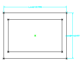
- Repeat these steps for top and right sides of the opening, in that order. Reposition the dimensions as needed so that they are easy to read. LenA3 and LenA4 are created for the long side and short side of the opening, respectively.
- Click View tab
 Views panel
  SW Isometric. This 3D view is better suited for the next steps.
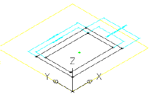
- Right-click Modifiers
 Add Extrusion. Click the outer rectangle. The Extrusion Modifier dialog box is displayed.
 - Verify that Type is set to Blind. Enter 8 for Distance and check the box next to Flip. Click OK. An extrusion modifier is created for the outer rectangle.
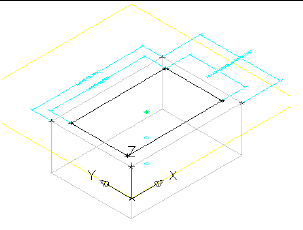
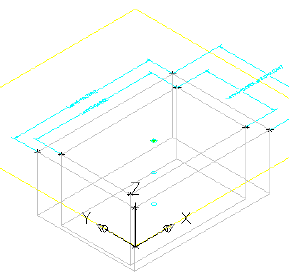
- Repeat these steps to create an Extrusion modifier for the inner rectangle using a distance of 9. An extrusion modifier is created for the inner rectangle.
- Right-click Model Dimensions
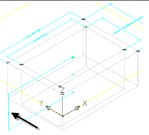
 Add Distance. Click one of the vertical edges of the outer box extrusion. Click a point to set the location of the dimension. LenB1 is created for the height of the frame section.
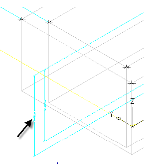
- Repeat this step for the inner box extrusion. LenB2 is created for the height of the opening extrusion.
- Expand Model Parameters, right-click Model Parameters, and then click Edit. The Model Parameters dialog box is displayed.
- Click LenB2, then click Calculator. Click Variable, then select LenB1. Enter +1 after LenB1 and then click OK, then Close.
This ensures that the extrusion for the opening is always deeper than the thickness of the frame. You could also have double clicked the cell in the Equation column and entered in your own formula.
- Right-click Modifiers
 Add Boolean Subtract. Click the outer box, then the inner box, and then press Enter. The inner box is subtracted from the outer box creating a third modifier which is the result of this action.
- Expand Modifiers. Notice the three modifiers that have been created. The Extrusion modifiers have been set to invisible by default as a result of the Subtract command. Rename the modifier named Subtract to Frame.
- Right-click Size Parameters and then click Edit Configuration. The Edit Part Sizes dialog box is displayed.
- Scroll to the right until you see the SBSL (Structure Length) column. Click Constant in the SBSL column, and change it to list. Do the same for the SBSW (Structure Width) Column. These parameters can now be specified by a list of values, rather than by a single constant.
- Click the drop-down arrow button next to Parameter Configuration, and select Values. Click the cell under SBSL, and then click the Edit button from the Edit Part Sizes dialog box toolbar. The Edit Values dialog box is displayed.
- Change the current value to 48. Then use the Add button to create values of 60, 72, 84, 96, 108, and 120. This makes it so that the Structure Length parameter can be adjusted in 12-inch increments.
- Repeat this step for the SBSW column, creating values of 36, 48, 60, and 72.
- Set the value of SBSL to 120 and the value of SBSW to 60. Click the Update Model button in the Edit Part Sizes dialog box toolbar. This updates the values under Model Parameters to match the Part Parameters.
- Click OK. Right-click Model Parameters and then click Edit. Click LenA1, and then click Calculator.
- Click Variable, and then click SBSL. Click OK, and then Close.
- Repeat these steps for LenA2, equating it to SBSW. The model is updated to reflect the changes to the dimensions.
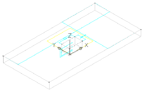
- Right-click Size Parameters and then click Edit Configuration. Click New. The New Parameter dialog box is displayed.
- Click Frame Length, and then click OK. Click New, then click Frame Width, OK. Two new parameters have been added: frame length (SFL) and frame width (SFW).
- Scroll to the right until you see the SFL and SFW columns. Change Constant to List for each of these columns. Then change the view to Values.
- Using the same procedure that was used for SBSL and SBSW, add values of 36, 48, 60, 72, 84, 96, and 108 for SFL. Add values of 24, 36, 48, and 60 for SFW.
These values are now controlled by lists that can ultimately be manipulated from within Autodesk Civil 3D when the part is in use.
- Click OK to close the Edit Part Sizes dialog box. Click Save Part Family. This saves the part as well as updates the Model Parameters to include the newly added Size Parameters.
- Right-click Size Parameters and then click Edit Values. Set the following values:
- SFL: 108
- SFW: 48
Click the Update Model button in the Edit Part Sizes dialog box toolbar, and then click OK. This updates the Model Parameter values so that they match the Part Parameter values where applicable.
- Expand Model Parameters, edit LenA3 and LenA4 to equate to SFL and SFW respectively. The model updates to reflect the changes to the dimensions.
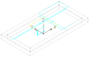
- Click Save Part Family. Remain in the Part Builder environment for the next exercise.
To continue this tutorial, go to Exercise 3: Defining the Vault Box Geometry.