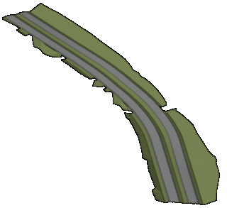
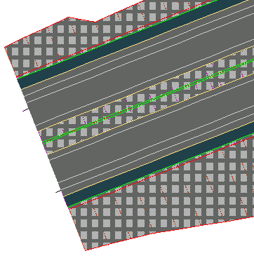
In this exercise, you will visualize the corridor using the rendering and hatching features in Autodesk Civil 3D.
Rendering a corridor requires that you assign an AutoCAD render material to each of the appropriate subassembly links. Rendering produces a realistic image of the corridor that is useful for on-screen presentations.
Applying hatching to a corridor requires that you apply a material area fill style to each of the appropriate subassembly links. Hatching produces a less realistic image of the surface than rendering, but hatching prints easily through AutoCAD.
This exercise continues from Exercise 2: Creating Corridor Surface Boundaries.
Apply 3D render materials to a corridor
- Open Corridor-5c.dwg, which is available in the tutorials drawings folder.
- In the drawing, select the corridor. Tip:
If you have difficulty selecting the corridor in the drawing, go to the ToolspaceProspector tab. Expand the Corridors collection. Right-click the corridor name and click Select.
First, you will apply render materials to the corridor link codes.
- Click Corridor tab
 Modify Corridor panel drop-down
  Edit Code Set Styles Find .
 - On the Edit Code Sets dialog box, under Code Set Style, make sure that All Codes is selected.
In the Render Material column, examine the materials that are set for the links that are included in the subassemblies for the current corridor. These materials will be displayed on each link when you render the corridor model:
- Daylight_Cut: Sitework.Planting.Grass.Short
- Daylight_Fill: Sitework.Planting.Grass.Short
- Ditch: Sitework.Planting.Grass.Thick
- Gravel: Sitework.Planting.Gravel.Mixed
- Median: Sitework.Planting.Grass.Short
- Pave: Sitework.Paving - Surfacing.Asphalt
- Slope_Link: Sitework.Planting.Grass.Short
- Click OK.
Hide and render corridor surfaces
- Click tab
 panel
panel  list
list  Corridor_3D View.
 The drawing is redrawn to a three-dimensional view of the corridor.
- In Toolspace, on the Prospector tab, expand the Surfaces collection.
- Right-click the Corridor - (1) Median surface. Click Surface Properties.
- In the Surface Properties dialog box, on the Information tab, change the Surface Style to Hide Surface. Click OK.
The Hide Surface style has all of its components turned off, which allows the surface’s render material to be effectively ignored. The rendering method used in this exercise applies render materials that are assigned to the subassembly link codes, and not the surface itself.
- Follow steps 2 and 3 to apply the
Hide Surface
style to the Corridor - (1) Pave and Corridor - (1) Top surfaces. Note:
The Corridor - (1) Datum surface already uses the Hide Surface style.
- On the command line, enter RENDER to render the corridor in 3D using the render materials that are applied to the subassembly links.

Next, you will view 2D hatch patterns on the corridor by applying shape styles to the appropriate subassembly links.
Apply 2D hatching to the corridor model
- Click tab
 panel
panel  list
list  Corridor_All.
 The drawing is redrawn to plan view.
- In the drawing, select the corridor.
- Click Corridor tab
 Modify Corridor panel drop-down
  Edit Code Set Styles Find.
 - On the Edit Code Sets dialog box, under Code Set Style, select All Codes With Hatching.
In the Material Area Fill Style column, notice that a fill has been applied to each of the subassembly links that you examined in the previous procedure. However, notice that Slope_Link does not have a Material Area Fill Style associated with it. In the next few steps, you will apply a style by modifying the code set style.
- Click
 Edit Current Selection. Note:
You can also open the Code Set Style dialog box from Toolspace on the Settings tab. Expand General
 Multipurpose Styles
 Code Set Styles. Right-click the appropriate code set style and click Edit.
 - In the Code Set Style dialog box, on the Codes tab, under Link, in the Slope_Link row, set the Material Area Fill Style to Strip Hatch .
- Click OK twice.
The material area fill styles are applied to the 2D corridor model. Zoom in on the beginning of the corridor to examine the hatch patterns.
