In this exercise, you will create a pipe network from an existing polyline. In this method of creating a pipe network, you use standard AutoCAD drawing commands to create a polyline, and then automatically place a pipe endpoint and structure at each polyline vertex.
You can create a pipe network from a variety of entities, including 2D and 3D polylines, AutoCAD lines and arcs, and feature lines. In this exercise, you will use an existing 2D polyline.
Create a pipe network from a 2D polyline
- Open drawing
Pipe Networks-1A.dwg, which is located in the
tutorials drawings folder.
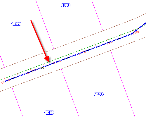
This drawing contains existing ground and corridor surfaces, alignments that represent intersecting road centerlines, parcels that represent property boundaries, and a polyline that represents the proposed pipe network layout. In the following steps, you will create an Autodesk Civil 3D pipe network from the polyline.
- Click
tab
 panel
panel  drop-down
  Find.
Find.
- Click the left end of the blue polyline that is near the center of the road.
The end that you click specifies the beginning of the pipe network. The network will flow away from this end.

- Press Enter to accept the flow direction.
- In the
Create Pipe Network From Object dialog box, specify the following parameters:
- Network Name: Storm Sewer Network
- Network Parts List: Storm Sewer
- Pipe To Create: 450 mm RCP
- Structure To Create: Eccentric Structure 1,500 dia 530 Frame 900 Cone
- Surface Name: First Street
- Alignment Name: First Street
- Erase Existing Entity: Selected
- Click
OK.
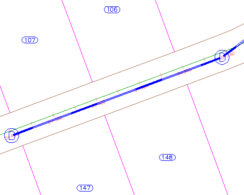
The pipe network is displayed in plan. A structure was created at each polyline vertex, and a pipe was created between the structures.

View the pipe network in profile
- Select a pipe and a structure.
- Right-click. Click Select Similar.
- Right-click. Click Draw Parts In Profile View.
- Click the First Street Profile view.
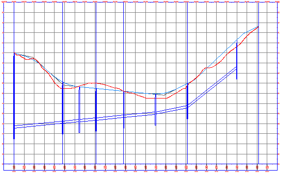
The pipes and structures are displayed in the profile view. Notice that as you specified, the direction of flow begins at the end station of the profile, and proceeds toward the beginning station.

- Press Esc.
Grip edit a network part
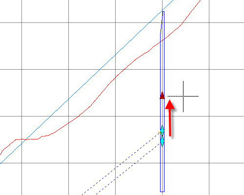
- Select the pipe on the far right side of the profile view.
- Click the
 grip. Drag the grip up to increase the invert elevation. Click to place the grip.
You can use grips to graphically change the position of pipes and structures in both plan and profile.

Edit network parameters
- Right-click. Click Edit Network.
- In the
Network Layout Tools toolbar, click the arrow next to
 .
.
These tools enable you to add pipes or structures to the network using the parameters you set on this toolbar.
- Click
 Pipe Network Vistas.
On the Panorama window, you use the Pipes and Structures tabs to edit pipes parametrically.
- On the Pipes tab, in the Pipe - (1) row, change the Start Invert Elevation value to 40.
- On the
Network Layout Tools toolbar, click
 Pipe Network Vistas.
The pipe invert elevation changes to the specified value.
To continue this tutorial, go to Exercise 2: Creating a Pipe Network by Layout.