In this exercise, you will change a profile style in two different ways.
First, you will change a profile style globally, which changes the profile’s appearance in all profile views. Then, you will learn how to override a profile style in a single profile view. Finally, you will hide the offset profiles.
This exercise continues from Exercise 1: Creating and Displaying Surface Profiles with Offsets.
Create a profile view
- Open Profile-2B.dwg, which is located in the tutorials drawings folder.
- Click
tab
 panel
panel  Drop-down
  Find.
Find.
- In the Create Profile View wizard, on the General page, under Select Alignment, click Ridge Road.
- Click Profile Display Options.
- Under Specify Profile Display Options, in the Style column, double-click the cell for the Left Offset profile.
- In the Pick Profile Style dialog box, select Standard. Click OK.
- In the Name column, select the first row. Hold down the Shift key, and then select the last row.
- In the Labels column, double-click one of the cells.
- In the Pick Profile Label Set dialog box, select <None>. Click OK.
- In the Create Profile View wizard, click Create Profile View.
- Pan to a location above the top of the first profile view, then click in the drawing.
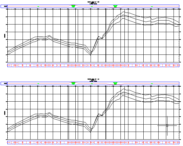
The new profile view, PV - (2), is drawn. The left offset profile is the same color as the other two profiles.
- Pan to the lower profile view, PV - (1).
Notice that its left offset line has also changed. The left offset profile changed because you changed the style of the profile, which affects every instance of the profile in every profile view in the drawing.

Change a profile style
- Select the PV - (1) profile view grid. Right-click. Click .
- Click the
Profiles tab.
On this tab, you can change properties of a profile line after it has been drawn in a profile view.
- On the Profiles tab, scroll until you can see the Style and Override Style columns.
- In the Override Style column for the Left Offset, double-click the check box.
- In the Pick Profile Style dialog box, select Existing Ground. Click OK.
- In the
Profile View Properties dialog box, click
Apply.
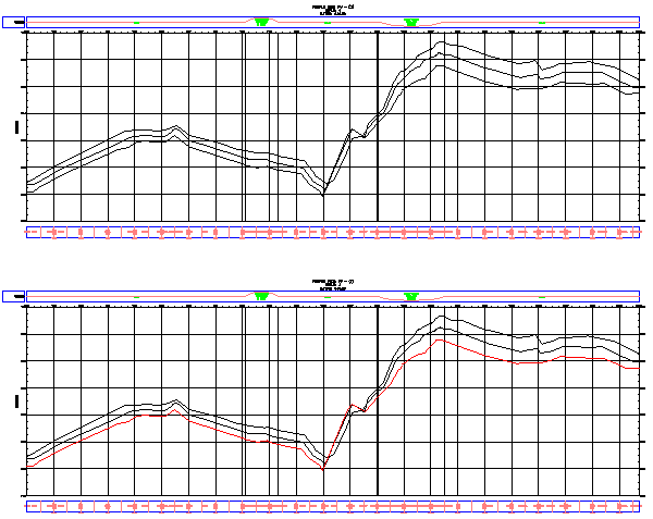
The Left Offset profile changes to red (reflecting the Existing Ground style) in profile view PV - (1), but not in PV - (2). The left offset profiles are different because you overrode the profile style for the particular profile view, but did not change the profile style. You can use a style override to preserve the profile style within a profile view, protecting it from later style changes.

Further exploration: In the Profile View Properties dialog box, clear the Override Style check box for the left offset. Click the Style column for this offset, change it to Standard, then click Apply. This changes the style for the profile and affects both profile views in the drawing.
Note:The left offset line is an approximate and static profile of the terrain along the power line. Optionally, if you wanted to see the actual profile, you could create a profile and profile view based on the Power Line alignment.
To continue this tutorial, go to Exercise 3: Reviewing Surface Profile Characteristics.