To add a free circular vertical curve between entities
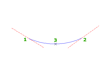
Add a free circular vertical curve between two tangents by specifying a parameter. Select a pass-through point in the drawing or specify a length or radius to define the curve.
The illustration shows a free circular curve between entities 1 and 2, passing through point 3.
- Click the profile. Click
 Find.
Find. - On the Profile Layout Tools toolbar, click
 Free Vertical Curve (Circular).
 - Select the first fixed or floating entity to which you want to attach the curve.
- Select the second fixed or floating entity to which you want to attach the curve.
- Enter one of the following parameters to complete the curve definition:
- Pass-Through Point: Enter P
- Radius: Enter R
- Length: Enter L
- K Value: Enter K
Note: If the profile was created using the criteria-based design feature, a default value is displayed on the command line. Minimum K values at given design speeds are specified in the design criteria file. Minimum curve length and radius are calculated from the minimum K value at the current design speed.
To add a free parabolic vertical curve between entities
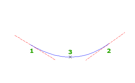
Add a free parabolic vertical curve between two entities by specifying a parameter. Select a pass-through point in the drawing or specify a K value, length, or radius to define the curve.
The illustration shows a free parabolic curve between entities 1 and 2, passing through point 3.
- Click the profile. Click Find.
- On the Profile Layout Tools toolbar, click
 Free Vertical Curve (Parabolic).
 - Select the first fixed or floating entity to which you want to attach the curve.
- Select the second fixed or floating entity to which you want to attach the curve.
- Enter one of the following parameters to complete the curve definition:
- Pass-Through Point: Enter P
- Radius: Enter R
- Length: Enter L
- K Value: Enter K
Note: If the profile was created using the criteria-based design feature, a default value is displayed on the command line. Minimum K values at given design speeds are specified in the design criteria file. Minimum curve length and radius are calculated from the minimum K value at the current design speed.
To add a free PVI-based parabolic vertical curve
Add a free parabolic vertical curve. Specify the curve by length, a pass-through point, or a K value.
The illustration shows a free curve between entities 1 and 2, specified with a length parameter 3.
- Click the profile. Click Find.
- On the Profile Layout Tools toolbar, click
 Free Vertical Parabola (PVI Based).
 - In the profile view, select a location near the PVI to which you want to add a curve.
- Enter one of the following parameters to complete the curve definition:
- Length: Enter L.
- Pass-Through Point: Enter P
- K Value: Enter K.
Note: If the profile was created using the criteria-based design feature, a default value is displayed on the command line. Minimum K values at a given design speed are specified in the design criteria file. Minimum curve length and radius are calculated from the minimum K value at the current design speed.
To add a free PVI-based asymmetrical vertical curve
Add a free asymmetrical vertical curve. You specify the length of the curve before the PVI and the length of the curve after the PVI.
The illustration shows an asymmetrical curve between tangents 1 and 2, with curve lengths 3 and 4.
- Click the profile. Click Find.
- On the Profile Layout Tools toolbar, click
 Free Asymmetrical Parabola (PVI Based).
 - In the profile view, select a location near the PVI to which you want to add a curve.
- Specify the length of the curve before the PVI by entering a value or by selecting two points in the drawing window.
If the first length you specify is too large for the asymmetric curve, you cannot enter the length for the second curve. The length of the first curve must be less than the station distance between the PVI you select and the station value of the previous PVI (or end station of the previous curve.)
- Specify the length of the curve after the PVI by entering a value or by selecting two points in the drawing window. Note: If the profile was created using the criteria-based design feature, a default value is displayed on the command line. Minimum K values at given design speeds are specified in the design criteria file. Minimum curve length and radius are calculated from the minimum K value at the current design speed.
To add a free PVI-based circular vertical curve
Add a free circular curve. Specify a radius, length, or pass-through point to define the curve.
The illustration shows a circular curve at PVI 1, passing through point 2.
- Click the profile. Click Find.
- On the Profile Layout Tools toolbar, click Free Circular Curve (PVI Based).
- In the profile view, select a location near the PVI to which you want to add a curve.
- Enter one of the following parameters to complete the curve definition:
- Radius: Enter R.
- Length: Enter L.
- Pass-Through Point: Enter P.
Note: If the profile was created using the criteria-based design feature, a default value is displayed on the command line. Minimum K values at given design speeds are specified in the design criteria file. Minimum curve length and radius are calculated from the minimum K value at the current design speed.
To add a free vertical curve by best fit
Add a free, three-point curve entity by best fit to a profile. You can define the best fit entity using a series of Autodesk Civil 3D points, existing entities, or clicks on screen.
The illustration shows a free vertical curve created by best fit between endpoints 1 and 2. The Xs indicates data points used to create the entity.
- Set the profile view style Vertical Exaggeration value to 1.0000.
- Click the profile. Click Find.
- On the Profile Layout Tools toolbar, click
 Free Vertical Curve - Best Fit.
 - Select an existing fixed or floating profile entity (the First Entity) from which to attach the best fit tangent.
- Select an existing fixed or floating profile entity (the Next Entity) to which to attach the best fit tangent.
- In the Curve by Best Fit dialog box, select one of the following:
- From COGO Points. In plan view, select two or more points. Enter G to select a point group or N to enter points by number.
- By Clicking On The Screen. Select a starting point and at least one other point. You can use OSNAP or transparent commands to select points.
- From Entities. Specify the tessellation and mid-ordinate tolerance settings. You can select one or more of the entity types listed on the command line. If you selected a profile entity, specify the starting and ending station on the Specify Station Range dialog box.
- In the Panorama window, use the Regression Data vista to modify the regression points.
As you highlight a row in the Regression Data vista, the corresponding regression point in the drawing window is highlighted in red.
- Create the curve:
- Click
 to create the curve and keep the Regression Data vista open.
 - Click
 to create the curve and close the Regression Data vista.
- Click