Use this dialog box to analyze and modify profile data in a layout profile.
When the Profile Entities vista and the Profile Layout Parameters dialog boxes are open, click any table row of PVI or sub-entity data in the Profile Entities vista to display the data in the Profile Layout Parameters dialog box. The data populates the Profile Layout Parameters dialog box in a vertical layout that you may find more convenient for analysis.
If
![]() PVI Based is selected in the Profile Layout Tools, the
Profile Layout Parameters dialog box displays PVI data. If
PVI Based is selected in the Profile Layout Tools, the
Profile Layout Parameters dialog box displays PVI data. If
![]() Entity Based is selected, the
Profile Layout Parameters dialog box displays entity data.
Entity Based is selected, the
Profile Layout Parameters dialog box displays entity data.
You cannot dock the Profile Layout Parameters dialog box, but you can pin or resize it.
This window remains open when you grip edit the profile or enter another command. The window closes when you either delete the currently selected profile, click the X button in the upper right-hand corner of the window, or click
![]() on the Profile Layout Tools toolbar.
on the Profile Layout Tools toolbar.

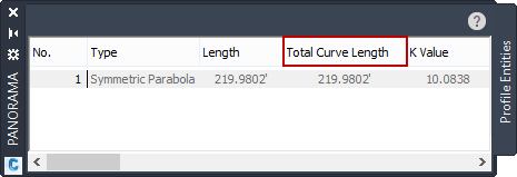
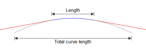
The Total Curve Length value shows the total vertical curve length, whereas the Length property shows the length of the solved portion of the curve geometry, such as when tangents are attached along the curves.

- The Total Curve Length property is available for all vertical curves.
- The Total Curve Length property is editable for fixed circular and fixed parabolic vertical curves that you create by specifying a high or low point.
Editing Parameter Values in the Profile Layout Parameters Dialog Box
You can edit available parameters by clicking in the Value column. If a parameter is uneditable, its name and values are displayed in a gray color.
When Entity Based is selected in the Profile Layout Tools, you can unlock and change the constraint type of free circular and parabolic vertical curves in the Profile Layout Parameters dialog box.
Design Speed
Displays the design speed of the current sub-entity. The design speed is set in the properties of the parent alignment.
Panels in the Profile Layout Parameters Dialog Box
If the profile uses design criteria, then the
Profile Layout Parameters dialog box contains up to three panels that can be collapsed by clicking
![]() . If design criteria has not been associated with the profile, then only the
Layout Parameters panel is available. If a sub-entity violates the specified design criteria, a
. If design criteria has not been associated with the profile, then only the
Layout Parameters panel is available. If a sub-entity violates the specified design criteria, a
![]() warning symbol is displayed next to sub-entities that violate the specified design criteria.
warning symbol is displayed next to sub-entities that violate the specified design criteria.
Design Criteria Panel
The following parameters are displayed only if design criteria has been associated with the profile.
Use the Design Criteria panel to apply design criteria that is different from the default values that have been set for the profile. To change a criterion value, click the Value cell in the appropriate row.
A
![]() warning symbol in the
Property column indicates that the sub-entity design violates the criteria set in the design criteria file. You can find the specific parameter that has been violated by examining the
Layout Parameters panel.
warning symbol in the
Property column indicates that the sub-entity design violates the criteria set in the design criteria file. You can find the specific parameter that has been violated by examining the
Layout Parameters panel.
- Minimum K For Stopping Sight Distance
-
Specifies the minimum K value for stopping sight distance at the specified design speed.
- Minimum K For Passing Sight Distance
-
Specifies the minimum K value for passing sight distance at the specified design speed.
- Minimum K For Headlight Sight Distance
-
Specifies the minimum K value for headlight sight distance at the specified design speed.
Layout Parameters Panel
Use this panel to examine and change the general layout parameters of the selected sub-entity.
Click
![]() Show More to expand the number of parameters that appear in the window. The default, collapsed view displays editable and other important parameters. Use the horizontal and vertical scroll bars when the list is longer or wider than the window.
Show More to expand the number of parameters that appear in the window. The default, collapsed view displays editable and other important parameters. Use the horizontal and vertical scroll bars when the list is longer or wider than the window.
When a design criteria file has been associated with a profile, the
Constraints column displays the value to which a given parameter is limited. The selected design criteria file defines the constrained values. When a parameter value violates the range displayed in the
Constraints column, a
![]() warning symbol appears next to the parameter name.
warning symbol appears next to the parameter name.
Design Checks Panel
The Design Checks panel displays the name and contents of the design check set that is associated with the profile.
When the sub-entity design violates a design check, a
![]() warning symbol appears next to the affected design check.
warning symbol appears next to the affected design check.