Use this dialog box to specify the replacement parts to use and to specify how the elevation of the replacement part is determined.
After the parts are replaced, the Design Check command is run automatically to alert you to any issues that may be introduced by the changes. Issues are marked with warning symbols.
Part Source
You can select replacement parts from either the current pressure network parts list or a specific parts catalog. The parts in the list or catalog that you select will be available for selection in the Replacement Part section of the dialog box.
- Parts List
- Specifies the current pressure network parts list for part swapping.
- Parts Catalog
- Specifies a specific parts catalog to use for part swapping.
Note: If you select a part from a parts catalog, the part is automatically added to the current parts list after the part swapping is completed if it has not already been added.
Replacement Part
Use these options to specify the replacement parts to use.
- Part Type
- Specifies the part type for the replacement part.
Note: Pressure pipes can only be replaced with other pressure pipes, fittings with other fittings, and appurtenances with other appurtenances. However, fittings are categorized into elbow, cross, and tee and parts of those subtypes can be swapped with each other. For example, an elbow fitting can be replaced with a cross or a tee fitting.
- Part Family
- Specifies the subset of the part types to use for the replacement part.
- Size
- Specifies the size to use for the replacement part.
Elevation Reference
You can use the Elevation Reference setting to specify how the elevation of the replacement part is determined. Path-based pressure networks can only use Outside Top as an Elevation Reference.
- If you specify a specific part
Elevation Reference (Outside Top, Crown, Centerline, Invert, Outside Bottom), the elevation of the point on the existing part will be used as the elevation of the same point on the new part.
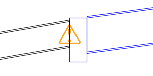
For example, if you select Centerline, the elevation of the centerline of the original parts is held as the elevation of the centerline of the replacement parts. In the following illustration which shows the effect in profile view, the blue fitting and pipe have been increased in size and Centerline was selected as the Elevation Reference.
- If you specify a surface and depth of cover, the elevation of the replacement part will be placed according to that surface elevation and cover depth.
For information about how the elevation reference of pressure networks is established when they are created, see "Establishing Elevation Information for the Pressure Network" in About Creating Pressure Networks in Plan View.
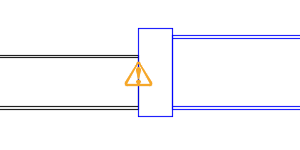
- Outside Top
- Specifies that the outside top of the new part is placed at the same elevation as the outside top of the existing part.
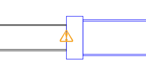
In the following illustration, the fitting and the pipe shown in blue were swapped to a larger size and their outside top elevations were held.
 Note: The illustrations in this section are shown in profile view. The black pipe on the left was left unchanged in order to illustrate the relative changes in the blue parts. The warning notifications are displayed because this leads to unequal diameters.
 - Crown
- Specifies that the crown of the new part is placed at the same elevation as the crown of the existing part.
In the following illustration, the fitting and the pipe shown in blue were swapped to a larger size and their crown elevations were held.
- Centerline
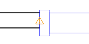
- Specifies that the centerline of the new part is placed at the same elevation as the centerline of the existing part.
In the following illustration, the fitting and the pipe shown in blue were swapped to a larger size and their centerline elevations were held.
- Invert
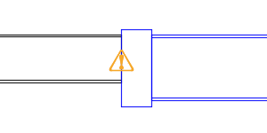
- Specifies that the invert of the new part is placed at the same elevation as the invert of the existing part.
In the following illustration, the fitting and the pipe shown in blue were swapped to a larger size and their invert elevations were held.
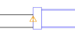
- Outside Bottom
- Specifies that the outside bottom of the new part is placed at the same elevation as the outside bottom of the existing part.
In the following illustration, the fitting and the pipe shown in blue were swapped to a larger size and their outside bottom elevations were held.
- Depth Of Cover
- Specifies that the outside top of the new part is set at an elevation below the reference surface. Enter the elevation in the
Depth Of Cover box.
Note: If the drawing does not contain any surfaces, this option is not available for selection.
In the following illustration, the fitting and the pipe shown in blue were swapped to a larger size and a depth of cover elevation was specified.