Use the Line By Direction and Distance command to draw AutoCAD LINE segments with precision, by referencing bearings and distances, locations selected in the drawing, or COGO points.
To use the Bearings option to define direction
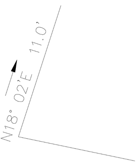
The following example shows how you can use the Line By Direction and Distance command to draw a line from the endpoint of a previously drawn line, at a bearing of N 18° 02' E, at a distance of 11.0 feet.
- In the
Toolspace, on the
Toolbox tab, expand
Miscellaneous Utilities
 Coordinate Geometry. Double-click
Line by Direction and Distance.
Coordinate Geometry. Double-click
Line by Direction and Distance.
- Select the end of a line from which the segment will be drawn.
- At the command line, enter the quadrant number (1=North East, 2=South East, 3=South West, 4=North West). For this example, enter 1.
- Enter the bearing, the direction of the line segment being drawn, in Decimal DMS format: DD.MMSS. For this example, enter 18.02.
- Enter the distance of the segment being drawn. For this example, enter 11.
- You can draw additional segments from the last endpoint or press Enter to end the command.
To use the Azimuth option to define direction
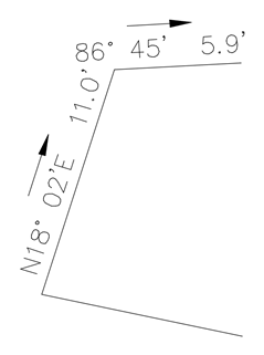
The following example shows how you can use the Line By Direction and Distance command to draw a line from the endpoint of a previously drawn line, at an azimuth of 86° 45', at a distance of 5.9 feet.
- In the
Toolspace, on the
Toolbox tab, expand
Miscellaneous Utilities
Coordinate Geometry. Double-click
Line by Direction and Distance.
- Select the endpoint of a previously drawn line to serve as the start point of the new line.
- At the command line, enter A to use the Azimuth mode.
- Enter an azimuth, the direction of the line segment being drawn, in Decimal DMS format. For this example, enter 86.45.
- Enter the distance of the segment being drawn. For this example, enter 5.9.
- You can draw additional segments from the last endpoint or press Enter to end the command.
To select locations on screen to define direction
You can select locations to define the direction when using the Line by Direction and Distance command. This is useful when you have previously drawn an entity on the screen, and you want to copy its direction for a new line, but start the new line from a different location. Turning on OSNAPs will ensure precise point selections.
- In the
Toolspace, on the
Toolbox tab, expand
Miscellaneous Utilities
Coordinate Geometry. Double-click
Line by Direction and Distance.
- Select the start point of the segment to be drawn.
- At the command line, enter P to use the screen point mode.
- Define a direction by selecting a starting location, and then select an ending location. Note the two screen selections may be anywhere in the model, and may not necessarily include the starting point of the line segment.
- Enter the distance of the segment being drawn.
The command continues, and additional segments will be drawn from the last endpoint.
To specify COGO point locations to define the direction and/or distance
When using the Line By Direction and Distance command, you can enter COGO point locations to define the direction, and/or the distance, in conjunction with standard Autodesk Civil 3D transparent commands. This is useful when you want to draw a line using the direction from a pair of points and you want the distance to equal the distance from a pair of points.
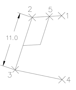
The following example shows how you can use the Line By Direction and Distance command to draw a line from point 5, parallel to line 2-3, with a distance equivalent to 2-1, and then a closing line parallel to 1-2 and closing on line 2-3.
- In the
Toolspace, on the
Toolbox tab, expand
Miscellaneous Utilities
Coordinate Geometry. Double-click
Line by Direction and Distance.
- At the command line, enter 'PN to use the point number transparent command.
- Enter the point number at the command line prompt. For this example, enter 5.
- At the command line, enter P to use the screen selection mode.
- The transparent command 'PN is still activated, so you can enter the point numbers to define the direction. For this example, enter 2 for the first direction point, and 3 for the second direction point.
- Enter the point numbers to define the distance. For this example, enter 2 for the first distance point, and 1 for the second distance point to draw the first segment.
- Enter P to re-enter point mode, and then enter the points to define the closure direction. For this example, enter 1 and 2.
- Define the length of the closure line. For this example, enter 5, and then 2.
- Press Enter to end the command.