To add a floating vertical tangent with a specified grade and length
Add a floating vertical tangent by specifying a grade and length.
- Click the profile. Click
 Find.
Find.
- On the
Profile Layout Tools toolbar, click
 Float Tangent (Grade, Length).
- Select the fixed or floating curve to which you want to attach the tangent.
- Specify the grade.
- Specify the length.
The specified grade is held if you grip edit the length of these tangents.
To add a floating vertical tangent with a specified pass-through point
Add a floating vertical tangent by specifying an attachment entity and a pass-through point.
The figure shows a floating tangent from an attached entity (1) to a pass-through point (2).
- Click the profile. Click
Find.
- On the
Profile Layout Tools toolbar, click
 Float Tangent (Through Point).
- Specify the fixed or floating curve to which you want to attach the tangent.
- Specify the pass-through point.
To add a floating vertical tangent by best fit
You can define the best fit entity using a series of Autodesk Civil 3D points, AutoCAD points, existing entities, or clicks on screen.
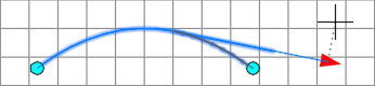
The illustration shows a floating vertical tangent created by best fit from an existing endpoint (1). The Xs indicate the data points used to create the entity.
- Set the profile view style Vertical Exaggeration value to 1.0000.
- Click the profile. Click
Find.
- On the
Profile Layout Tools toolbar, click
 Float Tangent - Best Fit.
- Select an existing fixed or floating profile entity to which to attach the best fit tangent.
- In the
Tangent by Best Fit dialog box, select one of the following:
- From COGO Points. In plan view, select two or more points. Enter G to select a point group or N to enter points by number.
- By Clicking On The Screen. Select a starting point and at least one other point. You can use OSNAP or transparent commands to select points.
- From Entities. Specify the tessellation and mid-ordinate tolerance settings. You can select one or more of the entity types listed on the command line. If you selected a profile entity, specify the starting and ending station on the Specify Station Range dialog box.
- In plan view, select two or more points. Enter
G to select a point group or
N to enter points by number.
As the points are selected in plan view, an X marks each regression point and a temporary, dashed tangent is displayed in the profile view.
- Press Enter to complete the command.
- In the
Panorama window, use the
Regression Data vista to modify the regression points.
As you highlight a row in the Regression Data vista, the corresponding regression point in the drawing window is highlighted in red.
- Create the tangent:
- Click
 to create the tangent and keep the
Regression Data vista open.
to create the tangent and keep the
Regression Data vista open.
- Click
 to create the tangent and close the
Regression Data vista.
to create the tangent and close the
Regression Data vista.
- Click