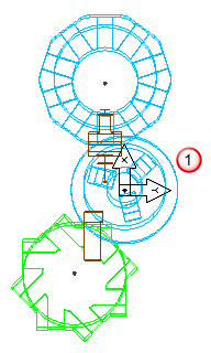
Lathe tool inserts cut the stock when they are parallel to the Setup's XZ plane. You must design your lathe machine so that a lathe tool in slot 1 can be moved into the XZ plane. FeatureCAM does not initially rotate the turret.
The following image shows a turret that is modeled incorrectly. The turret solid can't be moved such that the tool in slot #1 can cut in the XZ plane of the chuck without rotating the turret. In this situation, you should rotate the turret solid so that the tool is in the XZ plane of the chuck.
|
|
|
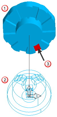
 Turret
 Chuck
Chuck Tool slot #1
FeatureCAM assumes that the tools point toward the center of the chuck. If that is not the case with the machine you are modeling, FeatureCAM needs the flexibility to move the turret so that the tool points toward the center of the chuck. In the example shown below, the tools are parallel to the XZ plane, but they do not line up with the chuck's center. In this case you should tell FeatureCAM that part of your machine moves in Y, when in reality, your machine cannot move in the Y axis. FeatureCAM must move the turrets in Y so the tools can be translated into the chuck's XZ plane.
|
|
|
It is not necessary or desirable to include the tool holders in the .md file. However, the tool blocks are part of the lathe machine.