The second stage of building your MD file is to set which solids work in which axes, using the Specify Movement dialog. You can define both rotary and linear axis movements for all types of machines, from simple 3-axis milling machines to full turn/mill machines.
In the following example, the z_slide solid is selected.
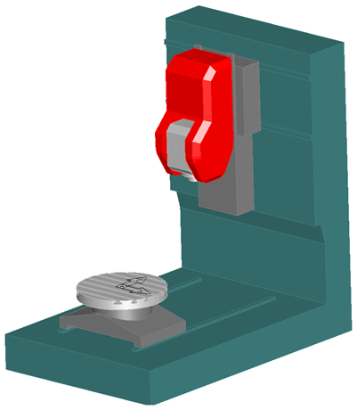
Given that this solid moves in the Z axis, the option Moves +delta Z is selected in the Tool quill section.
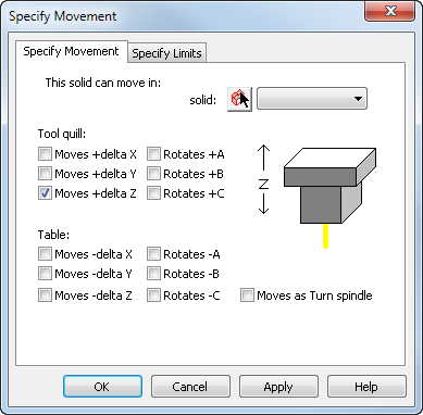
If this were a Z motion on the table instead, we would select the Moves -delta Z option in the Table section.
Although this component also moves in the X axis, that is not selected because the solid behind it controls that movement that relates to this solid when we set our parent/child relationships.
Movement for slant-bed turning machines
Many lathes and turn/mill machines have a slant-bed design that requires compound linear motion for the tool post. When you first create the machine design, it may be easiest to ignore the slant-bed to start with and just specify the X and Y motion in the machine coordinate system. You can disable collision warnings when testing the simulation to check more basic functions, such as whether the stock and tool interact properly. Then, go back and set up the correct motion for the slant-bed.