You can use the Dimensions tab of the Milling Feature Properties dialog to edit the physical properties of features. The Dimensions tab is different for each Milling feature type, and contains the attributes on the New Feature - Dimensions page of the New Feature wizard, as well as other advanced attributes.
If a dimension field has a blue label, you can click it and 'pick' the dimension from objects in the graphics window.
A — If the feature does not align with the X axis, enter the angle of the feature from the X axis.
Bottom Radius — Optionally set a bottom radius for the feature. The radius corresponds to the shape of the cutter. By default, the material is milled using a flat-bottomed mill, making stair-step passes when close to the radius. Then a rough and finishing pass is made with the radiused mill. The default value is 0, which cuts a square corner.
Boundaries — Click this button to open the Select Boundary Curves dialog, where you can select a curve to limit your feature.
C Angle — If Cut feature using Y Axis coordinates is selected, enter the spindle C angle at which to cut the feature.
Chamfer — Optionally enter the depth of a 45 degree chamfer, cut at the top of the feature. Leave this value at the default, 0, for no chamfer.
- 2D Chamfer — Create a chamfer on a curve in the XY plane.
- 3D Chamfer — Create a chamfer on a planar curve that is not in the XY plane, or is on a non-planar curve.
Check surfaces — Click this button to open the Select Check Surfaces dialog. This button is available only for NT toolpaths.
Corner radius — Enter the radius for all four corners of the Rectangular Pocket.
Curves — Click this button to display the Ordering dialog.
Custom — For Thread Mill features, select this option to enter the thread dimensions.
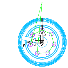
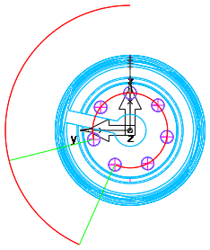
Cut feature using Y Axis coordinates — In Turn/Mill, 4 axis, or 5 axis parts with Z-indexing, select this option to cut in X and Y, or deselect it to rotate the part about the index axis.
|
Cut feature using Y Axis coordinates selected: |
Cut feature using Y Axis coordinates deselected: |
|
|
|
|
The tool moves in X and Y to cut the features. |
The part is rotated about the index axis to cut the features. |
Draft angle — Optionally set an angle for the feature wall. Use only positive numbers.
Face — For Groove features, this sets the Groove to cut on the XY plane of the current Setup.
Height — For Boss features, enter the height of the feature.
Inside/Outside — This sets the Groove to run on the inside or outside of a closed curve.
Length — Enter the X dimension of the feature.
Major Diameter — For OD Thread Milling features, enter the diameter of the outside of the threads.
Minor Diameter — For ID Thread Milling features, enter the diameter of the inside of the threads.
Pitch — Enter the pitch of the thread.
Radius — For Step Bore features, optionally set the bottom radius for the selected step. The radius corresponds to the shape of the cutter. By default, the material is milled using a flat-bottomed mill, making stair-step passes when close to the radius. Then a rough pass and a finishing pass are made with the radiused mill. The default value is 0, which cuts a square corner.
Simple — For Slot features, select this option to machine the feature by making a single pass down the center of it with a tool whose diameter is equal to the width of the feature.
Simple (Engrave) — For Groove features, select this option to machine the feature by making a single pass down the center of it, with a tool diameter equal to the width of the feature.
Single Point Bore — For Step Bore features, select this option to finish the step with a boring bar. This mills the step to a tight tolerance.
Standard Thread — For Thread Mill features, select this option and select a thread standard and size from the lists to use standard dimensions.
Stock Curve — Click this button to open the Select Stock Curve dialog, where you set the stock boundary for the feature.
Tapered — For Thread Milling features, select this option to create a tapered thread. Tapered taps are driven to a different depth than straight taps. for straight taps, a tip allowance is added to the thread depth so that the tool cuts the complete thread, this is not added for tapered taps so that the OD is not affected.
Thickness — For Face features, enter the height above the feature at which to start cutting.
Thread — Select a Left hand or Right hand thread. When viewed from the end of the part toward the chuck, on a left hand thread the tool winds counter-clockwise as it moves towards the chuck, on a right hand thread the tool winds clockwise as it moves towards the chuck.
Thread Height — Enter the height of the thread.
Thread Length — Enter the length of the thread.
Through — For Step Bore features, select this option to display the Step Bore feature without a bottom. This does not make the feature pass all the way through the stock. You must set the depth value deep enough.
Type — For Thread Mill features, select ID for an inner diameter thread or OD for an outer diameter thread.
Wrap feature around X/Y axis — This option is available for 4th-axis wrapping.
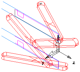
Wrap feature around Z axis — When using 4th-axis positioning, select this option to wrap the feature around the axis.
For example, this part has four Pockets:
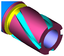
Select Wrap feature around Z axis and a 3D simulation looks like this:
Wrap Options — Click this button to display the Wrapped toolpath options dialog.
X Section — Click this button to open the Select Side Curve dialog, where you can select a curve to create a cross section for the wall of your feature.