A Points list Pattern enables you to specify the locations of individual points.
Select Points list pattern in the setup XY plane in the Patterns page of the New Feature wizard to display the Pattern - Dimensions page.
Use the tree view to move between the pattern properties, the object properties, and the manufacturing operation properties. Select the item in the tree view whose properties you want to see.
The different fields and buttons are:
A (Angle) — This sets the angle of rotation around the Z-axis, measured counter-clockwise from the X-axis, for the first object in the pattern.
Local offset — This controls whether the initial position of the object of the pattern is ignored. The position of the object is determined by its position in the pattern. If Local offset is selected, the feature's position influences the created pattern.
Using an object's position in a pattern can be tricky. For example, use local offsets to create a pattern of profiled features, such as a radial pattern of profile pockets. The recommended procedure is:
- Create the profile relative to the UCS.
- Enter the center of the pattern as XYZ coordinates.
- Enter 0.0 as the radius.
The pockets share the relative position to their center as the initial curve did to its UCS.
Object list — This highlights the name of the object repeated in the pattern. To change the object, click the down-arrow, then select the object to use in the pattern.
Point List — This displays the location and angle of the selected points. If you pre-selected holes or points, the order in which you picked these objects is reflected in the Point List. Clicking a row of the table displays the values in the X, Y, Z, and A options in the dialog. You can then modify the values using the Set, Add, Delete, Up, and Down options.
Pick Feature
 button — Use to determine which row of the point list contains the location of a specific feature. Click the button and then select a feature in the graphic window to highlight the row in the table containing that feature.
Set — Applies the values in the X, Y, Z, and A fields to the selected row in the Point List.
To change a location in the Point List table:
Click the row in the table you want to change. The values are inserted into the X, Y, Z, and A fields.
Change the values in the X, Y, Z, and A fields.
Click Set.
Add — Creates a new point in the Point List with the values in the X, Y, Z, and A fields.
Delete — Removes the selected row from the Point List.
Up — Moves the selected row of the Point List up one row in the list.
Down — This moves the selected row of the Point List table down one row in the table.
X, Y, Z — The X, Y, Z coordinates of a point.
A — The local Z rotation about the object's center.
Sorting
Sorting — This displays the Point List Sorting dialog. This dialog allows you to sort the objects in the following ways:
-
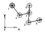
Shortest path — Starting with the first object in the list, a path is created by moving to the next closest object.
- X ascending — Objects are sorted in increasing order according to their X coordinates.
- X descending — Objects are sorted in decreasing according to their X coordinates.
- Y ascending — Objects are sorted in increasing order according to their Y coordinates.
-
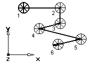
Y descending — Objects are sorted in decreasing according to their Y coordinates.
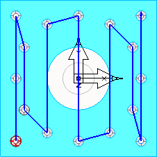
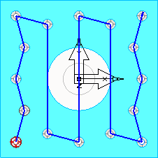
The left-hand figure shows a Shortest Path sorting. The figure on the right shows a y descending ordering.
The transitions for these four options can be Unidirectional or Bidirectional and you can edit the Location comparison tolerance to control how strict the comparisons are.
In this example, Unidirectional is selected. After cutting the three holes in the first 'column', the tool then rapids back down to the bottom of the next 'column' to cut the next feature:
These rapid moves are a particular problem with long parts, when the machine can be accelerating and decelerating over long distances.
Selecting Bidirectional lets the tool cut in both directions, and results in fewer rapid moves, for example:
With this example, you can make the toolpath yet more efficient by entering a Location comparison tolerance:
The tolerance lets FeatureCAM cut the next nearest feature, as long as it is within the tolerance.
Curves
Curves loads point locations from a linear profile. Click Curves to bring up the Select Curves dialog. Select the profiles that contain points you want to use as feature locations.