Radial Pattern Types
A Radial Pattern arranges the specified features spaced along the circumference of a circle. The spacing can be set so you only arrange features along an arc instead of the whole circle. Spacing and angles are set with dimensions settings.
Use the treeview pane to control whether you are looking at the pattern, the object, or the manufacturing operations for the pattern. Simply highlight your choice with the mouse. The rest of the dialog changes to reflect your choice.
|
|
|
 Number of features in the radial pattern, including the original feature
 Diameter of the radial pattern
 Spacing Angle between objects in the radial pattern
 Angle of the radial pattern position
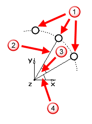
Angle — This sets the angle of rotation around the Z-axis, measured counter-clockwise from the X-axis, for the first object in the pattern.
Local offset — This controls whether the initial position of the object of the pattern is ignored. The position of the object is determined by its position in the pattern. If Local offset is selected, the feature's position influences the created pattern.
Using an object's position in a pattern can be tricky. For example, use local offsets to create a pattern of profiled features, such as a radial pattern of profile pockets. The recommended procedure is:
- Create the profile relative to the UCS.
- Enter the center of the pattern as XYZ coordinates.
- Enter 0.0 as the radius.
The pockets share the relative position to their center as the initial curve did to its UCS.
Object list — This highlights the name of the object repeated in the pattern. To change the object, click the down-arrow, then select the object to use in the pattern.
Diameter — This sets the overall diameter of the pattern.
Number — This sets the number of objects in the pattern.
Spacing Angle — This sets the space between the objects specified in degrees.
Cut feature using Y axis coordinates — In Turn/Mill, 4 axis, or 5 axis parts with Z-indexing, select this option to cut in X and Y, or deselect it to rotate the part around the index axis.
C Angle — If Cut feature using Y axis coordinates is selected, enter the spindle C angle at which to cut the feature.
Rotate C for each instance — If Cut feature using Y axis coordinates is selected, the stock is indexed for each instance of the pattern.
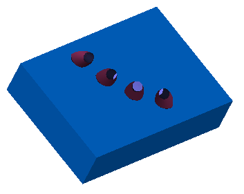
Radial in the setup XY plane — This option orients the features in the XY plane of the Setup. The two hole patterns in the image below are parallel to the Z- axis of the Setup.
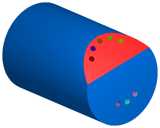
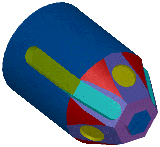
Radial around the index axis — This option aligns the features on the OD of the part, pointing toward the index axis. The slot and hole patterns in the figure below are radial.
Radial around arbitrary axis — This option positions the features around a specified origin in a specified axis. It is only available only for 5th axis machining.