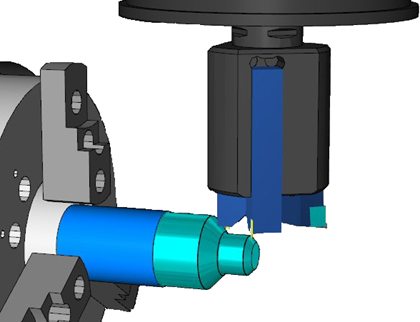
You can simulate mini-turrets, which are tools with multiple inserts where the tool rotates around the b-axis to access each insert. The tools are simulated simultaneously, which enables you to check for gouges with the tools that are not currently in use.

To simulate a mini-turret:
- In the Machine Design file, create a solid and UCS to represent the mini-turret, with the X axis of the UCS pointing towards the main spindle.
- Create a UCS for each tool location. The difference between the X axis of the tool location UCS and the turret UCS determines the angle that the mini-turret is rotated to use the tool.
- In the
Tool Block dialog:
- Select the turret solid under This solid is a tool block for solids.
- Select the turret UCS under This UCS will match up with the tool location on the turret.
- Use the Tool Locations tab to add each tool location UCS as a separate sub slot in the tool block.
- Click OK to close the dialog.
- Save the Machine Design file.
- In the FM document, use the Tool Mapping dialog to specify which tool block and sub slot to use for each feature.