The first step in creating a simulation machine is to specify the relationships between the different solids. In the image below, Table C is located on top of Table A. If Table A moves, then Table C should move with it. This is specified by indicating that Table A is the parent of Table C.
|
|
|
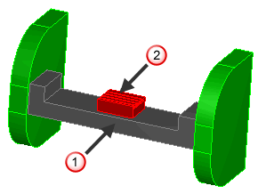
 Table A
 Table C
You specify this type of relationship in the Parent/Child Relationships dialog.
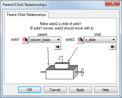
To open the Parent/Child Relationships dialog, select Machine Design > Parent/Child Relationships from the menu.
To use this dialog:
- Select the parent solid.
- Select the child solid.
- Click the Apply button.
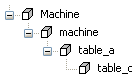
All solids must be associated with the machine. The machine solid in the Part View is not an actual solid, but it represents the top level of the machine. All solids must be connected to machine to be included in the simulation. The parent/child relationships are displayed in the Part View under the machine object. Here is an example of the hierarchy for a simple table-on-table machine.