You can use the Add Tool Location dialog to specify where the tool is held in a milling machine.
To display the Add Tool Location dialog, select Machine Design tab > Tools panel > Add Tool Location.
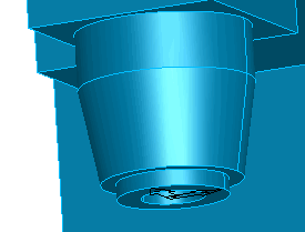
For most milling machines, the tool location is a single point at the center of the base of the spindle as shown below. The +Z axis points away from the part. The choice of the X and Y directions of the UCS are relatively arbitrary.
To use the Add Tool Location dialog to add a milling machine tool location:
- Specify the solid that represents the milling spindle that holds the tool.
Select a solid from the list, or click Pick Solid
 and select it in the graphics window.
- Select the UCS that represents the location where the milling spindle is attached to the machine.
Select Existing UCS and then pick the UCS from the graphics window, or select Create UCS/use alignment wizard and then use the wizard to create the UCS.
- Enter a Simulation C angle offset value. This is the angle between the tool post and the X axis. In some milling machines, you can perform turning with a C table, where you can turn in the YZ plane using a X angle offset of -90.
- Click
Apply.
A wireframe preview of the tool is displayed in the graphics window.
- Click OK to close the dialog.