Use the Gears dialog to create AGMA involute spur gears, one of the most common types of gear designs.
To create a gear curve:
- Select Construct tab > Curves panel > Other Methods > Gears to display the
Gears dialog.
The Gears dialog displays the Curve tab.
- Enter a Name for the curve.
- Enter a Fineness value to determine the number of control points in the tooth profile. The smaller the value; the greater the number of control points used to sample the curve.
- Enter the gear specification:
- Number of teeth — Enter the number of teeth on the gear.
- Pressure angle — Enter the acute angle, in degrees, between the tangent to the two base circles and a normal to the line connecting the gear centers.
- Tip fillet radius — Enter the radius of the tooth corner (see Diagram 2).
- Addendum — Enter the radial distance from the pitch circle to the outermost point of the tooth (see Diagram 2). Alternatively, select Outer diameter and enter the outside diameter of the gear.
- Dedendum — Enter the radial distance from the depth of the tooth trough to the pitch circle (see Diagram 2). Alternatively, select Root diameter and enter the root diameter of the gear.
- Pitch diameter — Enter the diameter of the pitch circle (see Diagrams 1 and 2). Alternatively, select Module and enter the pitch diameter divided by the number of teeth, or select Diametric pitch and enter the number of teeth divided by the pitch diameter.
- Root fillet radius — Enter the radius of the fillet at the bottom of each tooth (see Diagram 2).
-
Center point — Enter the coordinates for the center of the gear curve, or click
 and pick the curve in the Graphics window.
- Optionally click the Preview button to see the results of the current settings in the Graphics window.
- Select the Analysis tab to view the calculated dimensions of the gear, the calculated pin gauge diameter and the outside measurement over pins diameter.
- Select whether you want to create an External Gear or an Internal Gear.
- If you want to change the calculated diameter of the pin gauge, enter a new value in the Actual pin diameter box, and click Recompute.
- Click OK.
Note: The
Analysis tab is not displayed when you create a gear using the Curve Wizard.
Diagram 1:
|
|
|
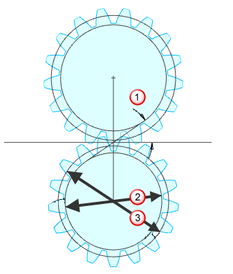
 Pressure angle
 Base diameter
 Pitch diameter
Diagram 2:
|
|
|
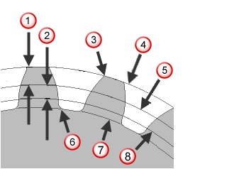
 Outside circle
 Pitch circle
 Root fillet radius
 Root circle
 Base circle