During machine simulation, FeatureCAM checks for collisions between solids. This is one of the main purposes of the simulation, but there are sometimes false errors that are not due to any error in the toolpaths or machine setup. These false errors often occur during development of the MD file when appropriate clearances have not been created between the moving parts of the machine.
There must be a small clearance between some of the moving parts so they do not collide in typical intended motion. If the mating faces are flat, there is little likelihood of a collision being signaled. However, when the faces are not flat, a collision is more likely because curved solids are approximated by (smaller) flat polygons during the simulation. The fineness of this approximation plays a role, and in some cases collisions can be erroneously signaled when the simulation is run at low resolution, where a higher resolution would not raise any error. It may be safer to provide relatively larger clearances for curved mating faces.
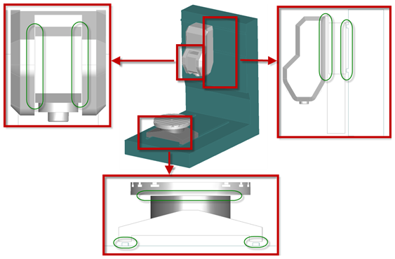
The image shows some examples of clearances. They are not much larger than 2mm each.
You cannot check for moving collisions until you have completed enough of the machine design to run tests with full machine simulation. However, when the solids for your machine are detailed, it may save some effort to perform an initial check of the solids that have close interactions. In some cases, the solids may intersect each other in the home position of the machine; these always produce false collision reports.
As well as checking them visually, you can check whether two solids intersect in the home position like this:
- Select Construct tab > Solids panel > Modifiers > Combine to open the Combine Solids dialog.
- In the Operation menu, select Intersection.
- Select the two solids you want to check as solid1 and solid2.
- Click the
Preview button.
- If you see the error Unable to construct object with these inputs, the solids do not have any overlapping volume.
- If not, the overlapping area is displayed in a dark blue preview in the graphics window, and you can adjust the view to determine what the problem is.
- Click the Cancel button to close the dialog without saving any changes.
If you find that there is an overlapping volume, you can correct it in several ways (depending on the amount of the overlap and the function of the components in conflict):
- Scale one component down by a small amount. For example, if you have a cylindrical piece with a Z axis that is just slightly too big, you could scale it non-uniformly in XY without changing any critical motion of the machine.
- Translate one component away from the collision area by a small amount, in a way that does not affect the simulation.
- Shrink or expand one of the solids to avoid the collision using Construct tab > Solids panel > Modifiers > Offset.
- Cut off the conflicting portion of the solid if it is not critical to the simulation. Cut with Parting Surface can be useful for this if you carefully construct a temporary surface to 'slice off' a small portion of the solid.
- Remodel the solid in a simpler way (possibly in a separate CAD system) to avoid the collision without compromising the fidelity of the simulation.