Polygonal method
This is the recommended method for solid and STL models; it uses the simulation engine to triangulate the file and create a profile curve. This example part is an imported .stl file.

With surface shading turned off, you can see the triangles that make up the .stl file:

To create the turned profile, select Construct tab > Curves panel > From Surfaces > Revolved Surface Boundary.
- In the Revolved Surface Boundary dialog, select Polygonal method.
- Optionally click the Tolerances button to change the default Triangle tolerance and Arcline approx. tolerance values.
- Click the
Preview button to see the boundary highlighted in dark blue in the graphics window:

FeatureCAM finds the correct profile height of the revolved square ends of the balustrade.
- Click
OK to create the curve.
You can use this curve to create a Turn feature.
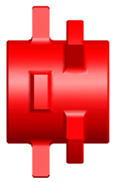
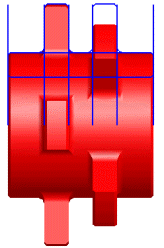
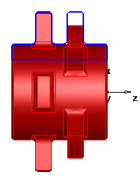
Solid method
Turned parts that are imported as solids are typically modeled using a series of surfaces of revolution. To accelerate the creation of turned features from these solid models, FeatureCAM provides a method of intelligently extracting geometry from these revolved solids. This functionality can be invoked from the process of importing a solid model into a turn or turn/mill document or by using the Revolved surface boundary curve creation tool. The images below, from left to right, show the initial solid model, the geometry created using the Surface method, and the geometry created using the Solid method. The solid method can only be used for solid models. You can see from the images below that the solid method provides better trimming of the geometry versus the surface method.