If you are modeling a lathe with a sub-spindle, you must identify the solid representing the sub-spindle. Specify the solid in the Sub-spindle dialog:
To open the Sub-spindle dialog, select Machine Design tab > Configuration panel > Sub-spindle.
To use this dialog:
- Select or pick the sub-spindle solid.
- Click the Apply button.
This dialog lets you designate which solid represents the sub-spindle. In a sense, this is akin to the Top-most Table dialog, that is, FeatureCAM has to know which solid holds the part when cutting on the sub-spindle.
The Local Coordinate System of the sub-spindle is important in terms of simulating sub-spindle positioning features. Typically the sub-spindle is positioned with respect to a machine coordinate system and not the part program (or Setup) zero. Set the Local Coordinate System's Z direction to match the machining sub-spindle commands. That is, if the machine's sub-spindle moves to the left in response to a negative W (or sometimes B), set the Z direction of the LCS pointing to the right (like the main spindle or turning main setup). Sometimes the positive W axis points to the left, that is, the machine moves to the left in response to a positive W (assuming W=0 is the home position). You can set the home W and max W in the .cnc file (Edit the .cnc file, and go to CNC-Info > Spindles).
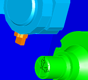
Here, the sub-spindle's LCSs (UCS shown) Z direction points to the right; this would be correct for a machine where a move the sub-spindle in to grab the part is a negative W and the move the sub-spindle home is a W of zero.