A Flowline milling operation is created using the following steps:
- Click the Features step.
- Click Surface Milling. Click Next.
- Select the part surfaces and click Next.
- Click Choose a single operation and click Next.
- Click Flowline and click Finish.
- Double-click the feature to edit it.
- In the operation tree-view, select flowline and select the Surface control tab.
- Click the Pick surface
 button and select the flowline guide surface.
 - The normal of the flowline guide surface must point toward the surfaces of the part. When you click the surface control tab, two arrows are displayed on the flowline guide surface. In the image below, the normal correctly points toward the part surfaces. If the normal must be reversed, click the Switch machining side
 button.
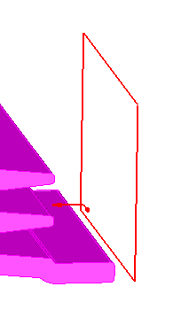
The arrows also indicate the starting point of the surface isolines and their direction. In the image above, the projected toolpath starts in the lower left and follows the rows of the surface. Use the Set isoline row/col
 button to change the starting point of the pattern and use the Cut direction
  button to change the direction of the cuts.