This tutorial guides you through the design of a simple 3-axis milling machine. We start the tutorial by opening an .md file that already contains all of the solids that represent the machine. This tutorial gives you instructions that help you establish the relationships between the different solids. You are guided in establishing movement, parent/child, and top-most table relationships.
Specifying movements
First, open 3axFerarriMachine Notcomplete.md from Examples\Machine Design\Mill\3-Axis.
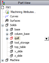
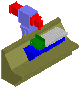
Let's specify how the machine moves. The first piece is the quill. The quill is represented as a single solid in the part file. You can see the quill displayed in the Part View and in the graphics window (shown in red here):
- Select Machine Design tab > Motion panel > Movement.
The Specify Movement dialog is displayed:
- For the solid, select quill and in the Tool quill section, select Moves +delta Y.
- Click the Apply button to save the setting for this solid.
- For the next solid, select z_slide and in the Tool quill section, select Moves +delta Z.
- Click the Apply button to save the setting for this solid.
- For the next solid, select x_slide and in the Table section, select Moves -delta X.
- Click the Apply button to save the setting for this solid.
- Click the OK button to close the dialog.
Defining parent/child relationships
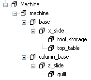
Next, we must define some parent-child relationships between various solids. The image below shows the first set of parent-child relationships that we must establish. The machine is the parent of column_base, which in turn is the parent of z_slide, which in turn is the parent of quill. If column_base moves, then z_slide must move with it, and if z_slide moves, then quill needs to go along as well.
|
|
|

 quill
quill
 z_slide
 column_base
- Select Machine Design tab > Configuration panel > Parent/Child Relationships.
The Parent/Child Relationships dialog is displayed.
- For parent/solid1, select machine and for child/solid2, select column_base. This sets machine as the parent of column_base.
- Click the Apply button to save the relationship.
- Repeat steps 2 and 3 to set the following:
- column_base as the parent of z_slide
- z_slide as the parent of quill
- machine as the parent of base
- base as the parent of x_slide
- x_slide as the parent of top_table
- x_slide as the parent of tool_storage
Tip: Use the left arrow button to quickly move the previous child solid to the parent column as you work down the list.Your machine hierarchy should look like this:
- Click the OK button to close the dialog.
Defining the stock attachment point
Next, we must define the top-most table so that FeatureCAM knows where to put the stock whenever this machine is used in simulation.
- Select Home tab > Create panel > UCS.
The UCS dialog is displayed.
- Click the
New button.
The New UCS dialog is displayed.
- In the
New UCS dialog:
- For the Name, enter UCS2.
- Select the Create from UCS option.
- Select the STOCK UCS.
- Click the OK button to close the New UCS dialog.
- In the
UCS dialog, ensure
UCS2 is selected as the
Current UCS and click the
Translate button.
The Translate dialog is displayed.
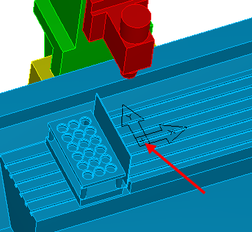
- In the
Translate along axis section, enter
100 for the
Z axis. This places it on the top of toptable as shown below.
- Click the OK button to save the settings and close the dialog.
- Click the Close button to close the UCS dialog.
- Select Machine Design tab > Configuration panel > Top most Table.
The Top-most Table dialog is displayed.
- In the
Top-most Table dialog:
- Select top_table as the solid.
- Select the Existing UCS option.
- Select UCS2 from the Existing UCS menu.
- Click the OK button to save the settings and close the dialog.
Defining the spindle attachment point
Next, we must define a place where the spindle mates to the quill.
- Select Home tab > Create panel > UCS.
The UCS dialog is displayed.
- Click the
New button.
The New UCS dialog is displayed.
- In the
New UCS dialog:
- For the Name, enter UCS3.
- Select the Create and go to alignment wizard option.
- Click the
OK button.
The Align UCS wizard opens.
- Select Revolved Surface and click the Next button.
- For the surface, select or pick
face_31 of the quill solid (shown below).
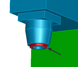
- Click the Finish button to save and close the wizard.
- Click the
Close button to close the
UCS dialog.
This new UCS is a mating point for the spindle.
- Select Machine Design tab > Tools panel > Add Tool Location.
The Add Tool Location dialog is displayed.
- In the
Add Tool Location dialog:
- Select the Add Tool Location tab.
- For the solid, select quill.
- Select the Existing UCS option.
- Select UCS3 from the Existing UCS menu.
- Click the OK button to save the settings and close the dialog.
Saving your new machine
Save your machine in a new file.
- Select File > Save As.
- Save the file with a new name so that you don't overwrite the example file and can run the tutorial again in future.
Using your new machine
To use your new machine:
- Open an .fm file.
- Select Home tab > Part Program panel > Setups.
The Setups dialog is displayed.
- Select the Setup that you want to simulate and click the
Edit button.
Note: For files where you simulate multiple Setups such as indexed or turn/mill parts, you should associate the machine file with the first Setup of a part.
- Click the Next button until you reach the Setup - Simulation Information page.
- Change the offset as needed. Usually, if the part-program zero is on the top of the part, then the offset is a negative Z.
- Select Always use this one and browse to the location of your new Machine Design file.
- Click the Finish button to save the settings and close the wizard.
- Select Machine Simulation mode in the Simulation toolbar and press Play.