You can recognize 2-axis Wire EDM features from curves. You can recognize a 4-axis Wire EDM feature from the faces of a solid model, or from surface boundaries.
To recognize a Wire EDM feature from solid faces
- Select Home tab > Part Program panel > Features.
- In the New Feature wizard, select a 4-axis feature type, select Extract with feature recognition, and click Next.
- Select For solid faces.
- Select Hide horizontal surfaces and enter an angle to hide surfaces within this angle from horizontal to make other surfaces easier to select.
- Click Next.
- In the Graphics window, select the faces you want to recognize features from and click
 in the
Solid Faces page.
in the
Solid Faces page.
- To set the feature height, select Manual and specify the top and bottom heights of the feature, or select Automatic to use the height of the selected faces as the height of the feature.
- Complete the wizard to create the feature.
To recognize a Wire EDM feature from surface boundaries
- Select Home tab > Part Program panel > Features.
- In the New Feature wizard, select a 4-axis feature type, select Extract with feature recognition, and click Next.
- Select:
- For all surfaces types to extract features from trimmed surfaces, or from a mix of trimmed and untrimmed surfaces.
- For untrimmed ruled surfaces to extract features from untrimmed surfaces.
- Select Hide horizontal surfaces and enter an angle to hide surfaces within this angle from horizontal to make other surfaces easier to select.
- Click Next.
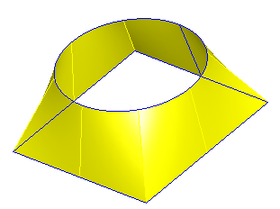
- The edges of all ruled surfaces in the model are displayed in blue.
- Click
Pick Curve
 .
.
- Select the curves of the feature in order.
- To reverse the direction of a curve, select it in the list and click
 .
.
- Complete the wizard to create the feature.
To recognize a Wire EDM feature from curves
- Select Home tab > Part Program panel > Features.
- In the New Feature wizard, select a 2-axis feature type, select Extract with feature recognition, and click Next.
- Select the geometry in the Graphics window to chain it into curves that represent the feature boundaries.
You can use the Feature/Geometry Edit bar at the bottom of the screen to change the curve chaining mode.
- Complete the wizard to create the feature.