Surface edges is useful for extracting trimming loops from 3D surface data, and projecting that curve onto the XY plane of the current UCS. You can use these curves to create 2.5D features.
IGES files often contain complete solid models of a part. Features such as pockets and holes are subtracted from part surfaces resulting in a collection of trimmed surfaces. In this model, the seven pockets have been subtracted from the surrounding surfaces.
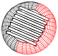
Rather than manufacturing all of these surfaces using 3D surface manufacturing techniques, you should use 2.5D Pocket features for each pocket.
Surface edges enables you to extract trimming curves from a collection of surfaces, join them into a curve and then project the curve onto the XY plane of your current UCS. You can then use this curve to create features.
To extract curves from 3D data:
- Select Construct tab > Curves panel > From Surfaces > Surface Edges to open the Surface Edges dialog.
- Optionally enter a curve name in the Name field, or leave the default name.
- Select the edge you want to use from the
Edges menu, or use the
Pick curve on surface
 button to select it in the graphics window. The edge is added to the table.
- The location of the pick is used to select a surface
and extract a trimming edge. Click the
Use next edge of surface
 button if you picked the correct surface, but the wrong edge.
- Continue selecting edges in order until you have selected all edges.
Use the Move item up
 and
Move item down
and
Move item down
 buttons to reorder the edges if necessary.
- If the edges are in the correct order, but the endpoints are matched up incorrectly, select the surface name in the table and click the
Reverse
 button.
- Select Connect start and end if you want the curve to be closed automatically.
- Select from the Project to UCS menu to have the curve automatically projected to the 2D XY plane of the UCS.
- If a hollow blue square is displayed at the intersection of two edges, then the edges have not quite matched up. You can correct this by either selecting the missing edge that will connect the endpoints, or if it is just an issue of floating point error, increase the Tolerance parameter.
- Click OK.