When you add a Deform Mesh node, the deformation mesh appears over the 3D model or surface. You can view the source mesh, the destination mesh, or both, to assist you as you deform the object. You can also turn both meshes off to view only the deformed object.
The deformation mesh consists of lattices and cells. You can divide the mesh into 1 to 100 lattices (to form a 3D grid of vertices), and each lattice can be divided by 1 to 3 cells. Increase the number of cells and lattices to deform specific areas of the object.
To add a deformation mesh:
- In the schematic, select the axis for the image, 3D model, or 3D text.
- Do one of the following:
- Drag the Deform Mesh node from the node bar and place it in the schematic.
- Drag the Deform Mesh node from the node bar and place it where you want it in Result view.
- Double-click the Deform Mesh node in the node bar. You do not need to be in Schematic view to add a node in this manner.
The deformation mesh is added to the selected object.

Image courtesy of Quietman
If you do not see the deformation mesh, follow the next steps.
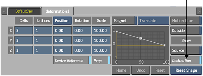
- Double-click the Deform Mesh node in the schematic.
The Deform Mesh menu appears.
- In the Deform Mesh menu, enable the Show Destination button to view the deformation mesh in the image window.