You define a 3D grid of vertices using lattices and cells to create a deformation mesh. You can divide the mesh into 1 to 100 lattices (to form the 3D grid of vertices), and each lattice can be divided by 1 to 3 cells. Increase the number of cells and lattices to deform specific areas of the object.
Note: You can only change the number of cells or lattices before you modify the parameters of the mesh. If you modify a parameter, for example, translate a tangent, you cannot change the number of cells or lattices.
To change the number of cells or lattices:
- In the image window, select the mesh.
- In the Deform menu, change the number of cells in the Cells X, Y, and Z fields. By default they are set to 3, 3, 3.
- In the Lattices X, Y, and Z field, change the number of vertices.
The cells or lattices are added to the deformation mesh.
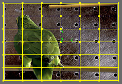
Image courtesy of Quietman
- To view the original mesh, enable Show Source.
- Use the Outside button to apply the deformation outside of the mesh (enabled) or constrain the deformation within the mesh (disabled).
To select points:
- From the Tools box, choose Select.
- Select the point(s):
- To select a single point, click the point.
- To select a range of points, hold the Ctrl key and draw a box around the points you want to select.
- To add a point or range of points to a selection, hold Shift+Ctrl and draw a box around the point(s) you want to add to the selection.
When you move a point, all selected points also move.
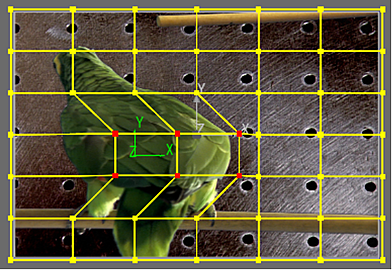
Image courtesy of Quietman
To transform a point on the mesh, drag it in the image window, or change the value in one of the X,Y or Z Translation fields.