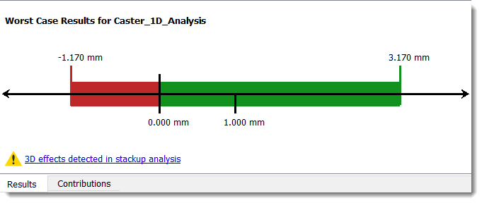
When Tolerance Analysis detects that the geometry included in the study is influenced by more than a single linear direction, the 3D effects detected in stackup analysis warning is displayed. The notification means that the results may underestimate the variation that will occur during production. If you see this message, you should think about the geometric relationships between the parts to determine if you need to perform additional analysis.
To understand the differences between 1D, 2D, and 3D tolerance analysis, see the section that compares them in About Tolerance Analysis.
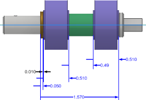
The following image is an example of a 1D problem. No warning message is displayed because the tolerance stackup of the parts occurs in a single linear direction.
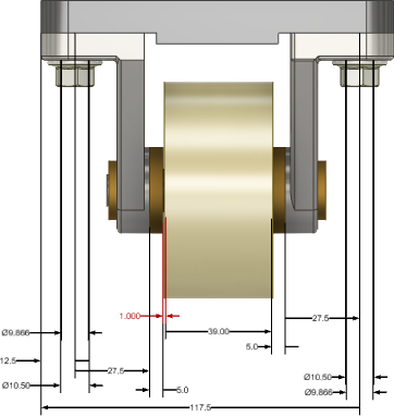
The analysis in the following image appears to be similar to the previous example, but there are conditions that can impact the translational 1D tolerance, so a warning is displayed.
Specifically, the tolerance analysis on the caster assembly accounts for all the vertical faces, but it does not account for potential variation in the top horizontal mounting faces. The warning alerts you to consider the influence of the other parts.
The following image shows an exaggerated example of what happens when the horizontal mounting faces rotate through their tolerance zones. The vertical legs of the brackets are no longer parallel to the wheel causing compression.
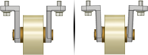
The warning typically calls attention to scenarios where the rotational variation of a surface has significantly more impact than the translational variation through the permissible tolerance limits. Because rotational effects are not included in the calculations, the warning alerts you that rotational effects may exist. The warning enables you to assess the severity of the requirement and determine if you need to use a 3D tolerance analysis tool or manually calculate the impact of the non-1D contributors and subtract the error from the acceptable stackup limits.
- When the surfaces defining the stackup distance of interest don't overlap.
- When some of the assembly constraints between parts are well outside the area of coverage for the surfaces selected for the stackup distance.
- When the size of the surfaces constraining the parts to one another are significantly smaller that the surface involved in the stackup distance definition.
- When a part is attached with a pattern of two or more fasteners and the measurement direction is in the plane of the mating faces to a surface far outside the pattern.
Tolerance Analysis can detect these conditions and more and provides a warning that the analysis might not be 1D.
Sometimes the warning appears in stackups that can be modeled with a 1D method. The most common situation is when parts are constrained in the assembly by several surfaces that interact in a similar way. However, when defining the loop for the stackup only one of the constraints is included in the loop definition.
For example, each end of a shaft mounted in a bearing or bushing. Another example is a circuit board mounted on several standoffs with multiple fasteners.
The warning appears because the 1D stackup definition involves the creation of a single dimension loop through the parts, and constraints that would normally help to stabilize the part in the assembly are not included in the stackup definition.