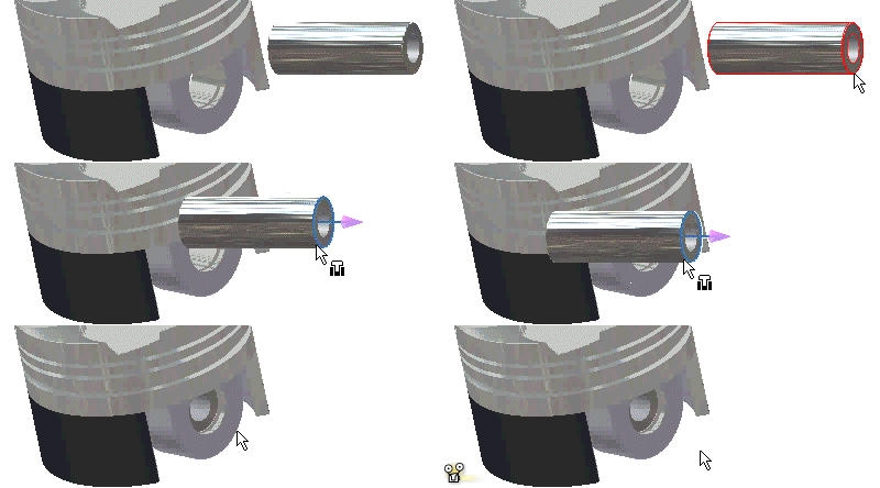
Assembly constraints maintain positions of components relative to one another in an assembly. Optionally, use the ALT-drag shortcut instead of using the Place Constraint dialog box or Assemble command.
- The selected geometry determines the type of constraint to apply:
- Click a planar face, linear edge, or axis to place a mate or flush constraint.
- Click a cylindrical face to place a tangent constraint.
- Click a circular edge to place an insert constraint.
- Hold down ALT, then select and drag the component into position. As you drag over features on other parts, the preview shows the constraint type.
- Optionally, press the spacebar to cycle through options for the constraint type:
- Select a mate or flush constraint.
- Select a tangent constraint inside or outside the selected cylindrical face.
- Select the direction of an insert constraint.
- Optionally, drag the component to a new position and cycle through constraint options.
- When the parts are positioned as needed, release the mouse button to create the constraint. A snap sound indicates that the components are in a constrained position.
If the face you must constrain to is hidden, pause long enough to display the Select Other command. Cycle through the available selectable options, then click the center dot to confirm the selection and place the constraint.
A constraint symbol is displayed with both components in the browser.
Tips, Shortcut Keys
Use the ALT-drag shortcut to infer constraints. Press ALT, and then drag a component into the appropriate position. The inferred constraints are previewed in the graphics window as you drag over the affected components.
When constraining components using the ALT-drag shortcut, you can change the constraint type after you start dragging the first part.
Release ALT, and enter a shortcut key:
- M or 1
- Changes to a mate constraint. Press the space bar to flip to a flush constraint.
- A or 2
- Changes to an angle constraint. Press the space bar to flip angle direction on the selected component.
- T or 3
- Changes to a tangent constraint. Press the space bar to flip between an inside and outside tangent constraint.
- I or 4
- Changes to an insert constraint. Press the space bar to flip insert direction.
- R or 5
- Changes to a rotation motion constraint. Press the space bar to flip rotation direction.
- S or 6
- Changes to a translation (slide) constraint. Press the space bar to flip slide direction.
- X or 8
- Changes to a transitional constraint.